

Contents
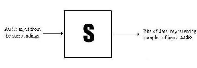
A PCM recorder
Analog audio signals to a stream of digits representing the analog audio
(digital audio). It is an Analog to Digital converter of the most basic kind
The conversion of an analog signal to a digital signal is a theoretically simple. What
happens is that the analog waveform is sampled periodically, and the samples are
digitized (converted into their binary equivalent ) one after the other.
Input : Analog audio(variation in the pressure of surrounding air with time), Sampling
rate and Bit-depth(sampling resolution)(most commonly used is 44.1kHz 16bit for audio
cd which can be changed as per requirements, for example some telephones use 10kHz
sampling whereas)
Output : Digital signals representing audio (music files typically .wav Microsoft .aiff
Apple Mac) These are the inputs for further compression using algorithms like those used
for .mp3, .au, .qt, .wma .ra etc)
Explanation of how it works
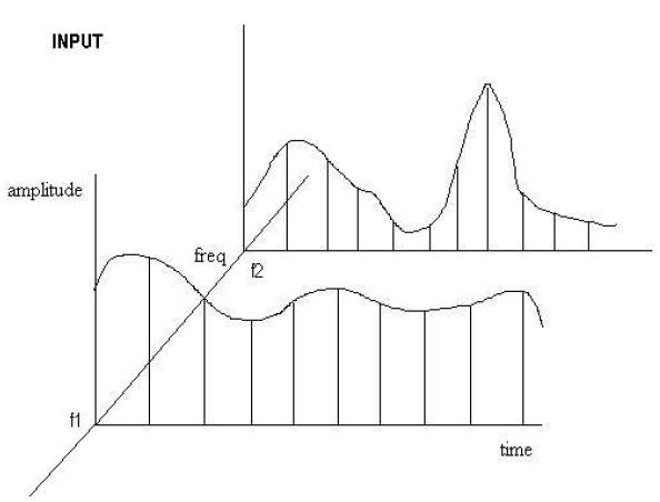
First stage : Microphone changes audio that is the pressure it senses into representative
analog voltage waveforms of suitable value thus acting like a system which passes on the
information of the audio heard to the sampling device (system).Note that we assume that
the output of the microphone (the voltage waveform) varies linearly with the air pressure.
Thus an example of the input to the microphone can be represented like this.
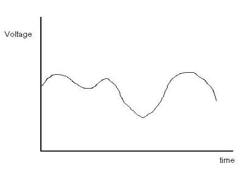
And the corresponding output of the microphone would be as shown below.
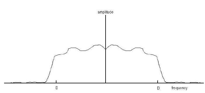
Second stage : A low pass filter (ideal one assumed) allows only frequencies of the
audible range though so that no aliasing effects take place due to any unwanted higher
frequencies) In practice a complex brick wall filter with sharp edges is used to filter
the input analog video.
The Fourier transform of this signal after passing through the filter is something like the
figure shown below.
The analog waveform which now is to be sampled ( The Voltage waveform ) which is the
output is shown below (Note this is not similar to the one shown above; it is a different
example)(Voltage versus time)
Third stage: Sampling of the voltage waveform takes place according to the input of
sampling frequency and number of bits (bit-depth) which we allocate to represent the
voltage level. How the rate and bit allocation of sampling varies the quality of sound is
that the higher the sampling frequency the better the original sound wave is replicated and
the higher the bit-depth the finer is the distinction between the different sounds. After a
time the difference is noticeable only to the trained ear and hence further increase in rate
of sampling or bit-depth is not required. This is due to the limited ability of the human
senses to recognize sound intensities and difference between frequencies.

