SQUID Magnetometer:
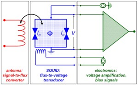
Figure 30.09: (left) Movement of samples in second order gradiometer and output signal [3], and (right) typical circuit of SQUID.
When the sample is moved up and down it produces an alternating magnetic flux in the pick-up coil. The magnetic signal of the sample is obtained via a superconducting pick-up coil with 4 windings.
This coil together with a SQUID antenna (red in right figure 30.09) is part of a whole circuit transferring the magnetic flux from the sample to an rf SQUID device which is located away from the sample in the liquid helium bath. This device acts as a magnetic flux-to-voltage converter (blue in above figure 30.09). This voltage is then amplified and read out by the magnetometer's electronics (green part).
Ref.[3]. http://squid-cmmp.blogspot.in/
Quiz 30:
(Q30.1) What is the advantage of VSM over VCM?
(Q30.2) How do the signal induce by the sample is probed in VSM?
(Q30.3) Is it possible to pick up the signal with only one secondary coil instead of set? Why?
(Q30.4) What is the purpose of using lock-in-amplifier in VSM circuit?
(Q30.5) Which type of gradiometer is good? Odd type or even type?