4.9 Circuit Representation of a Dielectric and Impedance Analysis
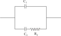
Data analysis after dielectric characterization often requires modeling of dielectrics which is helped by their representation as equivalent electrical circuits. Incidentally, a perfect dielectric material can be modeled by an equivalent RC parallel circuit as shown below.
| Figure 4.28 Equivalent circuit model of a dielectric |
Let us consider the admittance (Y) of the material representing the above circuit which is inverse of the impedance (Z), and is expressed as
 |
(4.108) |
where  and and  |
(4.109) |
Hence admittance now is
 |
(4.110) |
Now if we consider time constant for the segment R2C2 as τ2 = R2C2, then admittance can be written as
Now, since admittance can be related to the dielectric constant as
 |
(4.112) |
This gives
 and and  |
(4.113) |
which have the same form as Debye equations with C2 = (εs - ε∞) C0 and C1 = ε∞.
In 1941, K.S. Cole and R.H. Cole explained the behavior of dielectrics in alternating fields in which they plotted the electrical response of dielectric materials to the alternating fields as a function of frequency.
By this technique, they were able to identify and relate the observed relaxation effect with the atomic and microstructural features of the materials.
However, Cole and Cole used modified Debye equation which is
 |
(4.114) |
where α is a parameter which describes the distribution of relaxation times in the material.
For an ideal dielectric with well defined relaxation time i.e. α = 0, the system would be represented by the Debye equations i.e. equations (4.104-4.106).
As a result, if we plot εr'' (ω) vs εr' (ω) i.e. imaginary vs real part of the dielectric constant on a complex plane, we get a semi-circle.
|