|
Pipes In Parallel
- When two or more pipes are connected, as shown in Fig. 36.3, so that the flow divides and subsequently comes together again, the pipes are said to be in parallel.
- In this case (Fig. 36.3), equation of continuity gives
 |
(36.5) |
where, Q is the total flow rate and  and and  are the flow rates through pipes A and B respectively. are the flow rates through pipes A and B respectively.
- Loss of head between the locations 1 and 2 can be expressed by applying Bernoulli's equation either through the path 1-A-2 or 1-B-2.
- Therefore, we can write
Fig 36.3 Pipes in Parallel
and  |
Equating the above two expressions, we get -
where,  |
Equations (36.5) and (36.6) give -
 |
(36.7) |
where,  |
(36.8) |
- The flow system can be described by an equivalent electrical circuit as shown in Fig. 36.4.
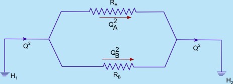
Fig 36.4 Equivalent electrical network system for flow through pipes in parallel
From the above discussion on flow through branched pipes (pipes in series or in parallel, or in combination of both), the following principles can be summarized:
- The friction equation must be satisfied for each pipe.
- There can be only one value of head at any point.
- Algebraic sum of the flow rates at any junction must be zero. i.e., the total mass flow rate towards the junction must be equal to the total mass flow rate away from it.
- Algebraic sum of the products of the flux (Q2) and the flow resistance (the sense being determined by the direction of flow) must be zero in any closed hydraulic circuit.
The principles 3 and 4 can be written analytically as
 at a node (Junction) at a node (Junction) |
(36.9) |
 in a loop in a loop |
(36.10) |
While Eq. (36.9) implies the principle of continuity in a hydraulic circuit, Eq. (36.10) is referred to as pressure equation of the circuit.
|


