|
Variation of Friction Factor
- In case of a laminar fully developed flow through pipes, the friction factor, f is found from the exact solution of the Navier-Stokes equation as discussed in lecture 26. It is given by
 |
(35.7) |
- In the case of a turbulent flow, friction factor depends on both the Reynolds number and the roughness of pipe surface.
- Sir Thomas E. Stanton (1865-1931) first started conducting experiments on a number of pipes of various diameters and materials and with various fluids.
Afterwards, a German engineer Nikuradse carried out experiments on flows through pipes in a very wide range of Reynolds number.
- A comprehensive documentation of the experimental and theoretical investigations on the laws of friction in pipe flows has been presented in the form of a diagram, as shown in Fig. 35.2, by L.F. Moody to show the variation of friction factor, f with the pertinent governing parameters, namely, the Reynolds number of flow and the relative roughness
 of the pipe. This diagram is known as Moody's Chart which is employed till today as the best means for predicting the values of f . of the pipe. This diagram is known as Moody's Chart which is employed till today as the best means for predicting the values of f .
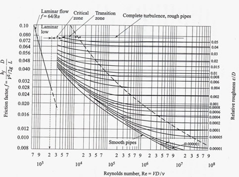
Fig. 35.2 Friction Factors for pipes (adapted from Trans. ASME, 66,672, 1944)
Figure 35.2 depicts that
- The friction factor f at a given Reynolds number, in the turbulent region, depends on the relative roughness, defined as the ratio of average roughness to the diameter of the pipe, rather than the absolute roughness.
- For moderate degree of roughness, a pipe acts as a smooth pipe up to a value of Re where the curve of f vs Re for the pipe coincides with that of a smooth pipe. This zone is known as the smooth zone of flow .
- The region where f vs Re curves (Fig. 35.2) become horizontal showing that f is independent of Re, is known as the rough zone and the intermediate region between the smooth and rough zone is known as the transition zone.
- The position and extent of all these zones depend on the relative roughness of the pipe. In the smooth zone of flow, the laminar sublayer becomes thick, and hence, it covers appreciably the irregular surface protrusions. Therefore all the curves for smooth flow coincide.
- With increasing Reynolds number, the thickness of sublayer decreases and hence the surface bumps protrude through it. The higher is the roughness of the pipe, the lower is the value of Re at which the curve of f vs Re branches off from smooth pipe curve (Fig. 35.2).
- In the rough zone of flow, the flow resistance is mainly due to the form drag of those protrusions. The pressure drop in this region is approximately proportional to the square of the average velocity of flow. Thus f becomes independent of Re in this region.
In practice, there are three distinct classes of problems relating to flow through a single pipe line as follows:
- The flow rate and pipe diameter are given. One has to determine the loss of head over a given length of pipe and the corresponding power required to maintain the flow over that length.
- The loss of head over a given length of a pipe of known diameter is given. One has to find out the flow rate and the transmission of power accordingly.
- The flow rate through a pipe and the corresponding loss of head over a part of its length are given. One has to find out the diameter of the pipe.
In the first category of problems, the friction factor f is found out explicitly from the given values of flow rate and pipe diameter. Therefore, the loss of head hf and the power required, P can be calculated by the straightforward application of Eq.(35.6b).
Now Let's do some Examples
|