Using the expression of e from Eq. (29.3), we have
 |
(29.4) |
The inlet blade angle  of a Francis runner varies of a Francis runner varies  and the guide vane angle angle and the guide vane angle angle  from from  . The ratio of blade width to the diameter of runner B/D, at blade inlet, depends upon the required specific speed and varies from 1/20 to 2/3. . The ratio of blade width to the diameter of runner B/D, at blade inlet, depends upon the required specific speed and varies from 1/20 to 2/3.
Expression for specific speed. The dimensional specific speed of a turbine, can be written as
Power generated P for a turbine can be expressed in terms of available head H and hydraulic efficiency  as as
Hence, it becomes
 |
(29.5) |
Again,  , ,
Substituting  from Eq. (29.2b) from Eq. (29.2b)
 |
(29.6) |
Available head H equals the head delivered by the turbine plus the head lost at the exit. Thus,
with the help of Eq. (29.3), it becomes
Substituting the values of H and N from Eqs (29.7) and (29.6) respectively into the expression  given by Eq. (29.5), we get, given by Eq. (29.5), we get,
Flow velocity at inlet  can be substituted from the equation of continuity as can be substituted from the equation of continuity as
where B is the width of the runner at its inlet
Finally, the expression for  becomes, becomes,
 |
(29.8) |
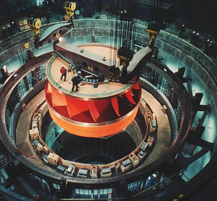
For a Francis turbine, the variations of geometrical parameters like  have been described earlier. These variations cover a range of specific speed between 50 and 400. Figure 29.2 shows an overview of a Francis Turbine. The figure is specifically shown in order to convey the size and relative dimensions of a typical Francis Turbine to the readers. have been described earlier. These variations cover a range of specific speed between 50 and 400. Figure 29.2 shows an overview of a Francis Turbine. The figure is specifically shown in order to convey the size and relative dimensions of a typical Francis Turbine to the readers.
Figure 29.2 Installation of a Francis Turbine |
|