Figure 30.3 shows a schematic diagram of propeller or Kaplan turbine. The function of the guide vane is same as in case of Francis turbine. Between the guide vanes and the runner, the fluid in a propeller turbine turns through a right-angle into the axial direction and then passes through the runner. The runner usually has four or six blades and closely resembles a ship's propeller. Neglecting the frictional effects, the flow approaching the runner blades can be considered to be a free vortex with whirl velocity being inversely proportional to radius, while on the other hand, the blade velocity is directly proportional to the radius. To take care of this different relationship of the fluid velocity and the blade velocity with the changes in radius, the blades are twisted. The angle with axis is greater at the tip that at the root.
| Fig. 30.3 A propeller of Kaplan turbine |
Different types of draft tubes incorporated in reaction turbines The draft tube is an integral part of a reaction turbine. Its principle has been explained earlier. The shape of draft tube plays an important role especially for high specific speed turbines, since the efficient recovery of kinetic energy at runner outlet depends mainly on it. Typical draft tubes, employed in practice, are discussed as follows.
Straight divergent tube [Fig. 30.4(a)] The shape of this tube is that of frustum of a cone. It is usually employed for low specific speed, vertical shaft Francis turbine. The cone angle is restricted to 8 0 to avoid the losses due to separation. The tube must discharge sufficiently low under tail water level. The maximum efficiency of this type of draft tube is 90%. This type of draft tube improves speed regulation of falling load.
Simple elbow type (Fig. 30.4b) The vertical length of the draft tube should be made small in order to keep down the cost of excavation, particularly in rock. The exit diameter of draft tube should be as large as possible to recover kinetic energy at runner's outlet. The cone angle of the tube is again fixed from the consideration of losses due to flow separation. Therefore, the draft tube must be bent to keep its definite length. Simple elbow type draft tube will serve such a purpose. Its efficiency is, however, low(about 60%). This type of draft tube turns the water from the vertical to the horizontal direction with a minimum depth of excavation. Sometimes, the transition from a circular section in the vertical portion to a rectangular section in the horizontal part (Fig. 30.4c) is incorporated in the design to have a higher efficiency of the draft tube. The horizontal portion of the draft tube is generally inclined upwards to lead the water gradually to the level of the tail race and to prevent entry of air from the exit end.
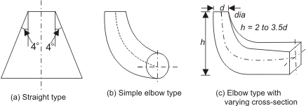 |
Figure 30.4 Different types of draft tubes |
|