Axial Flow Compressors
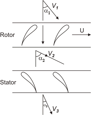
The basic components of an axial flow compressor are a rotor and stator, the former carrying the moving blades and the latter the stationary rows of blades. The stationary blades convert the kinetic energy of the fluid into pressure energy, and also redirect the flow into an angle suitable for entry to the next row of moving blades. Each stage will consist of one rotor row followed by a stator row, but it is usual to provide a row of so called inlet guide vanes. This is an additional stator row upstream of the first stage in the compressor and serves to direct the axially approaching flow correctly into the first row of rotating blades. For a compressor, a row of rotor blades followed by a row of stator blades is called a stage. Two forms of rotor have been taken up, namely drum type and disk type. A disk type rotor illustrated in Figure 9.1 The disk type is used where consideration of low weight is most important. There is a contraction of the flow annulus from the low to the high pressure end of the compressor. This is necessary to maintain the axial velocity at a reasonably constant level throughout the length of the compressor despite the increase in density of air. Figure 9.2 illustrate flow through compressor stages. In an axial compressor, the flow rate tends to be high and pressure rise per stage is low. It also maintains fairly high efficiency.
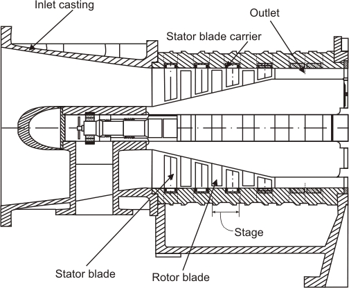 |
Figure 9.1 Disk type axial flow compressor |
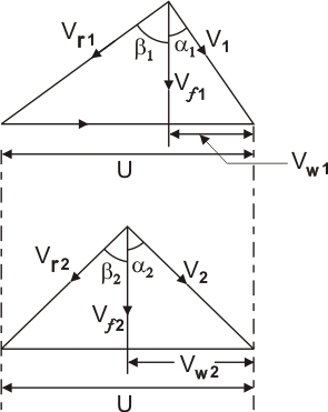
The basic principle of acceleration of the working fluid, followed by diffusion to convert acquired kinetic energy into a pressure rise, is applied in the axial compressor. The flow is considered as occurring in a tangential plane at the mean blade height where the blade peripheral velocity is U . This two dimensional approach means that in general the flow velocity will have two components, one axial and one peripheral denoted by subscript w , implying a whirl velocity. It is first assumed that the air approaches the rotor blades with an absolute velocity,  , at and angle , at and angle  to the axial direction. In combination with the peripheral velocity U of the blades, its relative velocity will be to the axial direction. In combination with the peripheral velocity U of the blades, its relative velocity will be  at and angle at and angle  as shown in the upper velocity triangle (Figure 9.3). After passing through the diverging passages formed between the rotor blades which do work on the air and increase its absolute velocity, the air will emerge with the relative velocity of as shown in the upper velocity triangle (Figure 9.3). After passing through the diverging passages formed between the rotor blades which do work on the air and increase its absolute velocity, the air will emerge with the relative velocity of  at angle at angle  which is less than which is less than  . This turning of air towards the axial direction is, as previously mentioned, necessary to provide an increase in the effective flow area and is brought about by the camber of the blades. Since . This turning of air towards the axial direction is, as previously mentioned, necessary to provide an increase in the effective flow area and is brought about by the camber of the blades. Since  is less than is less than  due to diffusion, some pressure rise has been accomplished in the rotor. The velocity due to diffusion, some pressure rise has been accomplished in the rotor. The velocity  in combination with U gives the absolute velocity in combination with U gives the absolute velocity  at the exit from the rotor at an angle at the exit from the rotor at an angle  to the axial direction. The air then passes through the passages formed by the stator blades where it is further diffused to velocity to the axial direction. The air then passes through the passages formed by the stator blades where it is further diffused to velocity  at an angle at an angle  which in most designs equals to which in most designs equals to  so that it is prepared for entry to next stage. Here again, the turning of the air towards the axial direction is brought about by the camber of the blades. so that it is prepared for entry to next stage. Here again, the turning of the air towards the axial direction is brought about by the camber of the blades.
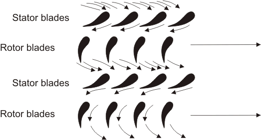 |
Figure 9.2 Flow through stages |
Figure 9.3 Velocity triangles |
Two basic equations follow immediately from the geometry of the velocity triangles. These are:
 |
(9.1) |
 |
(9.2) |
In which  is the axial velocity, assumed constant through the stage. The work done per unit mass or specific work input, w being given by is the axial velocity, assumed constant through the stage. The work done per unit mass or specific work input, w being given by
 |
(9.3) |
This expression can be put in terms of the axial velocity and air angles to give
 |
(9.4) |
or by using Eqs. (9.1) and (9.2)
 |
(9.5) |
|