This input energy will be absorbed usefully in raising the pressure and velocity of the air. A part of it will be spent in overcoming various frictional losses. Regardless of the losses, the input will reveal itself as a rise in the stagnation temperature of the air
 . If the absolute velocity of the air leaving the stage . If the absolute velocity of the air leaving the stage  is made equal to that at the entry. is made equal to that at the entry.  , the stagnation temperature rise , the stagnation temperature rise
 will also be the static temperature rise of the stage, will also be the static temperature rise of the stage,  , so that , so that
 |
(9.6) |
In fact, the stage temperature rise will be less than that given in Eq. (9.6) owing to three dimensional effects in the compressor annulus. Experiments show that it is necessary to multiply the right hand side of Eq. (9.6) by a work-done factor λ which is a number less than unity. This is a measure of the ratio of actual work-absorbing capacity of the stage to its ideal value.
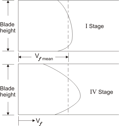
The radial distribution of axial velocity is not constant across the annulus but becomes increasingly peaky (Figure. 9.4) as the flow proceeds, settling down to a fixed profile at about the fourth stage. Equation (9.5) can be written with the help of Eq. (9.1) as
 |
(9.7) |
| |
Figure 9.4 Axial velocity distibutions |
Since the outlet angles of the stator and the rotor blades fix the value of
 and and
 and hence the value of and hence the value of  . Any increase in . Any increase in  will result in a decrease in will result in a decrease in  and vice-versa. If the compressor is designed for constant radial distribution of and vice-versa. If the compressor is designed for constant radial distribution of  as shown by the dotted line in Figure (9.4), the effect of an increase in as shown by the dotted line in Figure (9.4), the effect of an increase in  in the central region of the annulus will be to reduce the work capacity of blading in that area. However this reduction is somewhat compensated by an increase in in the central region of the annulus will be to reduce the work capacity of blading in that area. However this reduction is somewhat compensated by an increase in
 in the regions of the root and tip of the blading because of the reduction of at these parts of the annulus. The net result is a loss in total work capacity because of the adverse effects of blade tip clearance and boundary layers on the annulus walls. This effect becomes more pronounced as the number of stages is increased and the way in which the mean value varies with the number of stages. The variation of in the regions of the root and tip of the blading because of the reduction of at these parts of the annulus. The net result is a loss in total work capacity because of the adverse effects of blade tip clearance and boundary layers on the annulus walls. This effect becomes more pronounced as the number of stages is increased and the way in which the mean value varies with the number of stages. The variation of  with the number of stages is shown in Figure. 9.5. Care should be taken to avoid confusion of the work done factor with the idea of an efficiency. If with the number of stages is shown in Figure. 9.5. Care should be taken to avoid confusion of the work done factor with the idea of an efficiency. If
 is the expression for the specific work input (Equation. 9.3), then is the expression for the specific work input (Equation. 9.3), then
 is the actual amount of work which can be supplied to the stage. The application of an isentropic efficiency to the resulting temperature rise will yield the equivalent isentropic temperature rise from which the stage pressure ratio may be calculated. Thus, the actual stage temperature rise is given by is the actual amount of work which can be supplied to the stage. The application of an isentropic efficiency to the resulting temperature rise will yield the equivalent isentropic temperature rise from which the stage pressure ratio may be calculated. Thus, the actual stage temperature rise is given by
 |
(9.8) |
and the pressure ratio  by by
 |
(9.9) |
where,
 is the inlet stagnation temperature and is the inlet stagnation temperature and  is the stage isentropic efficiency. is the stage isentropic efficiency.
| Figure 9.5 Variation of work-done factor with number of stages |
|

 ,
,  = 43.9 ° and
  = 13.5 °. The factor
 = 0.86 and
  = 0.85 and inlet temperature
  is 288 K. Calculate the pressure ratio.

 of air has been taken as 1005 J/kg K]