1.1 Type of construction
1.1.1 Check Valves
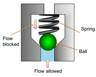
Figure 5.4.1 Inline check valve
These are unidirectional valves and permit the free flow in one direction only. These valves have two ports: one for the entry of fluid and the other for the discharge. They are consists of a housing bore in which ball or poppet is held by a small spring force. The valve having ball as a closing member is known as ball check valve. The various types of check valves are available for a range of applications. These valves are generally small sized, simple in construction and inexpensive. Generally, the check valves are automatically operated. Human intervention or any external control system is not required. These valves can wear out or can generate the cracks after prolonged usage and therefore they are mostly made of plastics for easy repair and replacements.
An important concept in check valves is the cracking pressure. The check valve is designed for a specific cracking pressure which is the minimum upstream pressure at which the valve operates. The simplest check valve is an inline check valve as shown in Figure 5.4.1. The ball is held against the valve seat by a spring force. It can be observed from the figure that the fluid flow is not possible from the spring side but the fluid from opposite side can pass by lifting the ball against. However, there is some pressure drop across the valve due to restriction by the spring force. Therefore these valves are not suitable for the application of high flow rate. When the operating pressure increases the valve becomes more tightly seated in this design.
The advantages of the poppet valves include no leakage, long life and suitability with high pressure applications. These valves are commonly used in liquid or gel mini-pump dispenser spigots, spray devices, some rubber bulbs for pumping air, manual air pumps, and refillable dispensing syringes. Sometimes, the right angle check valve as shown in Figure 5.4.2 is used for the high flow rate applications. The pressure drop is comparatively less in right angle check valve.
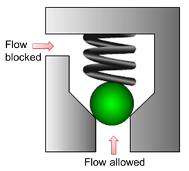
Figure 5.4.2 Right angle check valve
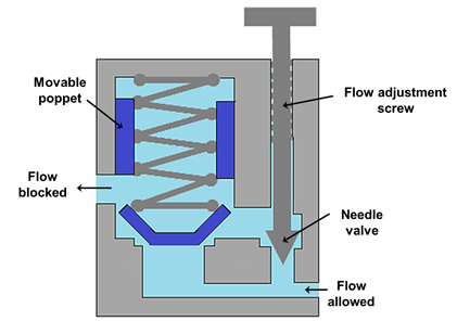
Figure 5.4.3 Restriction check valve
When the closing member is not a ball but a poppet energized by a spring is known as poppet valve. The typical poppet valve is shown in Figure 5.4.3. Some valves are meant for an application where free flow is required in one direction and restricted flow required in another direction. These types of valves are called as restriction check valve (see Figure 5.4.3). These valves are used when a direction sensitive flow rate is required. For example, the different actuator speeds are required in both the directions. The flow adjustment screw can be used to set the discharge (flow rate) in the restricted direction.
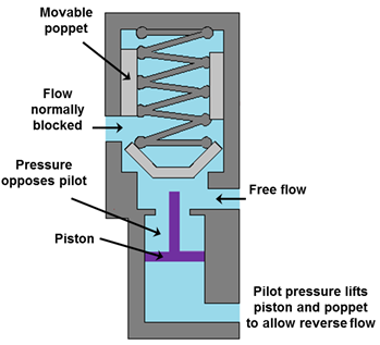
Figure 5.4.4 Pilot operated check valve
Another important type of check valve known as pilot operated check valve which is shown in figure 5.4.4. The function of the pilot operated check valve is similar to a normal check valve unless it gets an extra pressure signal through a pilot line. Pilot allows free flow in one direction and prevents the flow in another direction until the pilot pressure is applied. But when pilot pressure acts, the poppet opens and the flow is blocked from both the sides. These valves are used to stop the fluid suddenly.