3. Pulse modulation
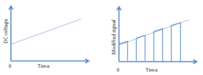
Figure 2.7.4 Pulse amplitude modulation
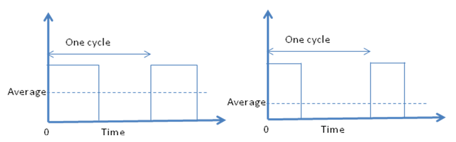
Figure 2.7.5 Pulse width modulation
During amplification of low level DC signals from a sensor by using Op-amp, the output gets drifted due to drift in the gain of Op-amp. This problem is solved by converting the analogue DC signal into a sequence of pulses. This can be achieved by chopping the DC signal in to a chain of pulses as shown in Figure 2.7.4. The heights of pulses are related to the DC level of the input signal. This process is called as Pulse Width Modulation (PWM). It is widely used in control systems as a mean of controlling the average value of the DC voltage. If the width of pulses is changed then the average value of the voltage can be changed as shown in Figure 2.7.5. A term Duty Cycle is used to define the fraction of each cycle for which the voltage is high. Duty cycle of 50% means that for half of the each cycle, the output is high.