1. Protection
In many situations sensors or transducers provide very high output signals such as high current or high voltage which may damage the next element of the control system such as microprocessor.
1.1 Protection from high current:
The high current to flow in a sensitive control system can be limited by:
- Using a series of resistors
- Using fuse to break the circuit if current value exceeds a preset or safe value
1.2 Protection from high voltage:
Zener diode circuits are widely used to protect a mechatronics control system from high values of voltages and wrong polarity. Figure 2.7.1 shows a typical Zener diode circuit.
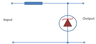
Figure 2.7.1 Zener diode circuit diagram
Zener diode acts as ordinary or regular diodes upto certain breakdown voltage level when they are conducting. When the voltage rises to the breakdown voltage level, Zener diode breaks down and stops the voltage to pass to the next circuit.
Zener diode as being a diode has low resistance for current to flow in one direction through it and high resistance for the opposite direction. When connected in correct polarity, a high resistance produces high voltage drop. If the polarity reverses, the diode will have less resistance and therefore results in less voltage drop.
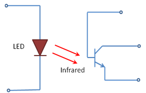
Figure 2.7.2 Schematic of an Optoisolator
In many high voltage scenarios, it is required to isolate the control circuit completely from the input high voltages to avoid the possible damage. This can be achieved by Optoisolators. Figure 2.7.2 shows the typical circuit of an Optoisolator. It comprises of a Light emitting diode (LED) and a photo transistor. LED irradiates infra red due to the voltage supplied to it from a microprocessor circuit. The transistor detects irradiation and produces a current in proportion to the voltage applied. In case of high voltages, output current from Optoisolator is utilized for disconnecting the power supply to the circuit and thus the circuit gets protected.