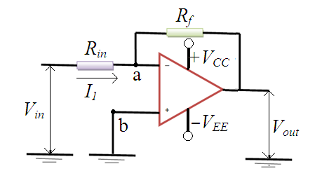
Figure 2.6.3 Inverting op-amp
1.2 Amplification of input signal by using Op-amp
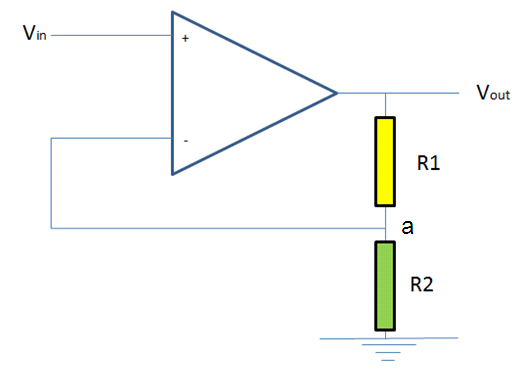
Figure 2.6.4 Amplification using an Op-amp
Figure 2.6.4 shows a configuration to amplify an input voltage signal. It has two registers connected at node a. If we consider that the voltage at positive terminal is equal to voltage at negative terminal then the circuit can be treated as two resistances in series. In series connection of resistances, the current flowing through circuit is same. Therefore we can write,
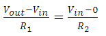 |
(2.6.5) |
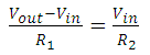 |
(2.6.6) |
Thus by selecting suitable values of resistances, we can obtain the desired (amplified/attenuated) output voltage for known input voltage.
There are other configurations such as Non-inverting amplifier, Summing amplifier, Subtractor, Logarithmic amplifier are being used in mechatronics applications. The detail study of all these is out of scope of the present course. Readers can refer Bolton for more details.