1.1 Operational amplifier (op-amp)
Operational Amplifier is a basic and an important part of a signal conditioning system. It is often abbreviated as op-amp. Op-amp is a high gain voltage amplifier with a differential input. The gain is of the order of 100000 or more. Differential input is a method of transmitting information with two different electronic signals which are generally complementary to each other. Figure 2.6.2 shows the block diagram of an op-amp. It has five terminals. Two voltages are applied at two input terminals. The output terminal provides the amplified value of difference between two input voltages. Op-amp works by using the external power supplied at Vs+ and Vs- terminals.
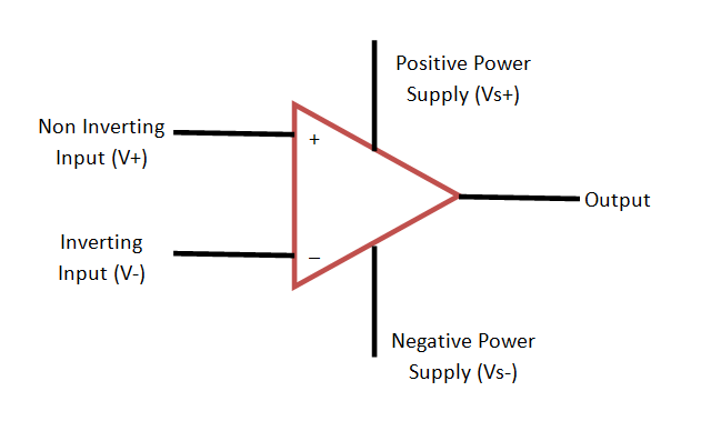
Figure 2.6.2 circuit diagram of an Op-amp
In general op-amp amplifies the difference between input voltages (V+ and V-). The output of an operational amplifier can be written as
| (2.6.1) |
where G is Op-amp Gain.
Figure 2.6.3 shows the inverting configuration of an op-amp. The input signal is applied at the inverting terminal of the op-amp through the input resistance Rin. The non-inverting terminal is grounded. The output voltage (Vout) is connected back to the inverting input terminal through resistive network of Rin and feedback resistor Rf . Now at node a, we can write,
| (2.6.2) |
The current flowing through Rf is also I1, because the op-amp is not drawing any current. Therefore the output voltage is given by,
| (2.6.3) |
Thus the closed loop gain of op-amp can be given as,
| (2.6.4) |
The negative sign indicates a phase shift between Vin and Vout .