where [P]n is a point matrix and [S]n is a state vector. It should be noted that now the point matrix is complex in nature due to damping term.
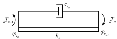
Figure 6.49 A free body diagram of nth shaft segment
The characteristics of the shaft segment at station n (Fig. 6.49) are represented in the equation describing the torque applied to the shaft at the location of rotor n, as
(6.105) |
While the torque transmitted through the shaft is the same at both ends, i.e.,
(6.106) |
Substituting equations (6.101) and (6.102), in equations (6.105) and (6.106), we get
(6.107) |
and
(6.108) |
Combining equations (6.107) and (6.108), we get
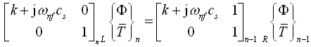 |
(6.109) |
which can be written as
![]()
with
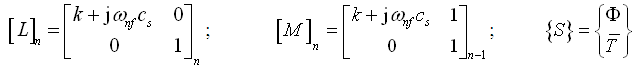
which can be simplified as
(6.110) |
with 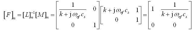
where [F]n is a field matrix at station n. From equations (6.104) and (6.110), we get
(6.111) |
with
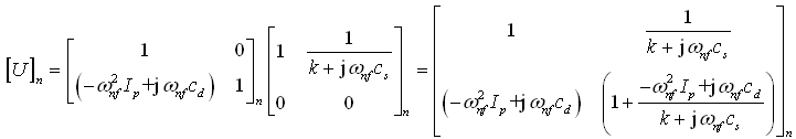
where [U]n is a transfer matrix between stations n and (n-1). Once we have the point and field matrices, remaining analysis will remain the same for obtaining natural frequencies, mode shapes, and forced responses. Only difference would be that now we need to handle the complex numbers. Such analysis with damped multi-DOF could also be performed relatively simpler way with FEM and it will be discussed subsequently.