A brief history of rotor dynamics field has been documented in the present review. It reviews early development of simple rotor models starting from the Rankine to Jeffcott rotor models and physical interpretations of various kinds of instabilities in rotor-bearing systems. It also reviews developments of analysis methods for the continuous and multi-degrees-of freedom systems to allow practicing engineers to apply these methods to real turbo-machineries. It also summarises work on conditioning monitoring and the recent trends in the area of rotor dynamics.
Before starting discussion of the subject of rotor dynamics it would be pertinent to ask why this subject is required to be studied and how it differs from the conventional structural dynamics? Since rotating machinery is omnipresent right from house-hold machinery, automotives, marines to space applications and hence understanding the dynamic behaviour of rotating machinery is crucial for long life of the machinery and safety of humans. Rotor dynamics deals with these aspects and hence its study is very important for designers and practicing engineers. As compared to structural vibrations the rotor dynamics differs in several ways: (i) rotating machineries have inherent forces and moments due to dynamics of various machine elements or faults in occur them, (ii) gyroscopic effects which is predominant at higher speeds makes natural frequency speed dependent, (iii) bearings and seals also makes natural frequency of the rotor system speed dependent, moreover, it also makes system unstable, (iv) the asymmetry in rotors due to operational requirements (such as keyways or slots in rotors) causes the rotor instability, (v) the internal damping (hysteretic or friction between two mating parts in rotors) makes the system unstable, and (vi) there are several other reasons for the instability due to working fluid interactions with rotor components (e.g., blades). Aforementioned reasons make the rotor dynamics more challenging as compared to the structural dynamics.
Rotating machinery have applications with varied speed of operations: 3-4 rpm for cement factory kilns, 3000 rpm for steam turbine-generator, 20,000 rpm for jet-engines for aero planes, 50, 000 rpm for cryogenic-fuel pumps in rockets, to 1, 00, 000 rpm for vacuum pumps for centrifuges. Similarly, these rotating machineries have varied power capacities: 0.5-3 W for household appliances, 50 MW for jet-engines, 600-1200 MW for steam turbines. Depending on the application the length of the rotor could be as long as 50 m (for steam turbine-generator), 2 m for jet engines, 0.5 m for cryogenic pumps and few centimeters for helicopters.
A rotor is a body suspended through a set of cylindrical hinges or bearings that allow it to rotate freely about an axis fixed in space (Figs. 1.1 and 1.2). Rotors can often be represented as a single beam or series of beam elements and rigid discs. The beam is frequently considered as flexible. Rigid discs are mounted on the flexile beam either by shrink-fit or by other mechanical means. Practically, a rigid disc model represents flywheels, blades, cranks, rotary wings, coupling, disc brakes, impellers, rolling bearings, etc. Engineering components concerned with the subject of rotor dynamics are rotating components of machines, especially of turbines, generators, motors, compressors, blowers and the like. The parts of the machine that do not rotate are referred to with general definition of the stator. The machine element that allows relative motion of the rotor relative to the stator is called the bearing. Rotors of machines have, while in operation, a great deal of rotational energy, and a small amount of vibrational energy. It is very evident from the fact that a relatively small gas turbine propels a huge aircraft. The purpose of rotor dynamics as a subject is to keep the vibrational energy as small as possible. In operation rotors undergoes the transverse (lateral or bending), longitudinal (axial), and torsional (or twisting) vibrations; individually or in combination.
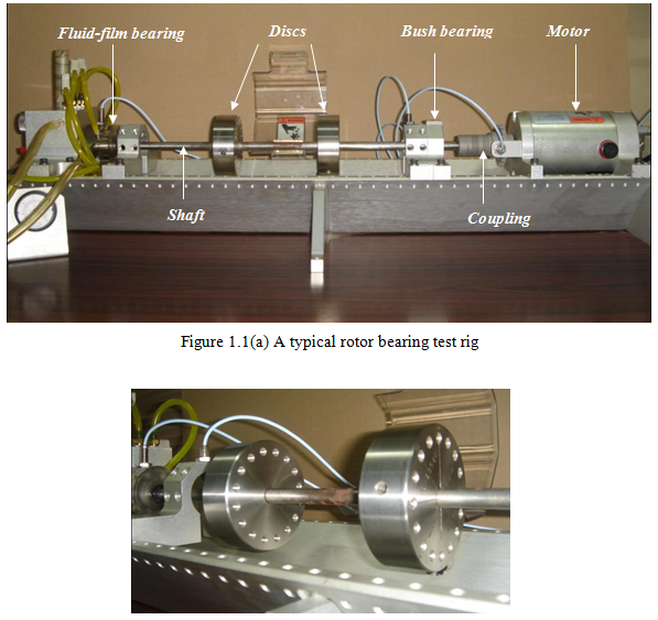
Figure 1.1(b) A close view of a rotor consisting of two discs mounted on a flexible shaft