In the closed return tunnel, air is passed from the exit of the test section back to the inlet by a series of turning vanes at the corner of the tunnel. Exiting the diffuser, the air is returned to the nozzle and back through the test section. Air is continuously circulated through the duct work of the closed return tunnel. To prevent condensation in the test section because of low pressure, the air entering the tunnel is often passed over a dryer bed. There is usually an additional throat placed in the tunnel downstream of the test section to decelerate the supersonic flow to subsonic. The continuous closed-circuit supersonic tunnel has some advantages and some disadvantages relative to the intermittent tunnel. Advantages of the closed return tunnels include longer run times relative to the blow down tunnel, superior flow quality in the test section, flow turning vanes in the corner and flow straighteners near the test section ensure relatively uniform flow in the test section, lesser noisy operation, the test section can be designed for high Mach numbers (M>4) and large-size models, low operating costs. Also once the air is circulating in the tunnel, the fan and motor only needs to overcome losses along the wall and through the turning vanes. The fan does not have to constantly accelerate the air.On the same grounds disadvantages of the closed return tunnels include higher construction cost because of the added vanes and ducting. This tunnel must be designed to purge exhaust products that accumulate in the tunnel.
38.3 Supersonic Diffuser
Supersonic diffuser with second throat should be designed critically because increasing diffuser efficiency will lower the power requirement considerably. The first throat is the one upstream of the test-section through which the flow accelerates.
An ideal diffuser would be characterised by an isentropic compression to lower velocities. This situation is sketched in Figure 38.3. Because the flow is isentropic the stagnation pressures at both ends of the diffuser would be equal. But it is extremely difficult to slow a supersonic flow without generating shock waves in the process. Moreover, in practical situation, the flow is viscous. As a result there will be an entropy increase within the boundary layers on the walls of the diffuser.
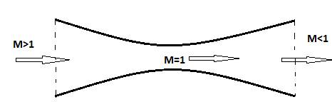
Fig. 38.3. Schematic of ideal diffuser.
An actual supersonic diffuser is sketched in figure 38.4. Here, the incoming flow is slowed by a series of reflected oblique shocks, first in a convergent section and then in a constant area throat (called as second throat). Due to the interaction of shock waves with the boundary layer near the wall, the reflected shock pattern eventually weakens and becomes diffused. Finally, the subsonic flow downstream of the constant area throat is further slowed by moving through a divergent section.
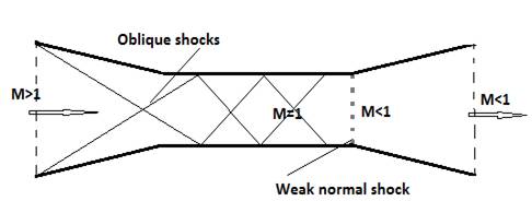
Fig. 38.4. Schematic of ideal diffuser.
It may be shown that a shock wave in the converging portion of the second throat would be unstable, and in practice the second-throat Mach number is chosen large enough for the breakdown shock system to be located well downstream of the throat, to ensure stability under all operating conditions.
When the tunnel is started up, the second throat must be rather larger than the first throat in order to choke first, so that supersonic flow can be established in the test-section.