38.1 Indraft supersonic wind tunnel.
Schematic of a typical indraft supersonic wind tunnel is shown in Fig. 38.1.
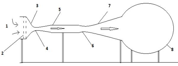
Fig. 38.1. Schematic of indraft tunnel.
Following are the components of this tunnel.
1. Air inlet
2.Settling chamber
3.Nozzle
4.Sonic throat
5.Test-section
6.Second throat
7.Diffuser
8.Vacuum chamber.
Some blowdown tunnels, called as indraft tunnels, do not use a high pressure chamber, but use atmosphere as the resevoir. The indraft tunnel uses the low pressure (vacuum) chamber downstream of the test section to produce flow.
During the opertation of this tunnel, air from the atmosphere enters the nozzle and gets expanded to require Mach number defined by the area ratio of the nozzle. Further flow of the air from the test section, second throat decelerates the air and let it fill the vacuume chamber. The main advantage of this configuration is that the conditions in the inlet remain constant and there is no need for a pressure regulator. The disadvantage is that the pressure ratio across the test section is usually lower than a closed configuration and therefore the maximum Mach number (M>2) is not possible.
38.2 Closed Continuous Wind Tunnel
Typical continuous wind tunnel is as shown in Fig.38.2.
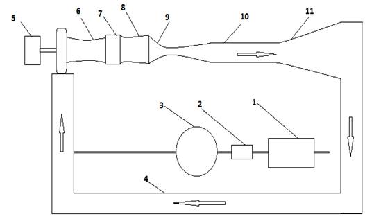
Fig. 38.2. Schematic of closed circuit continuius wind tunnel.
Following are the parts of this wind tunnel.
1. Air compressor
2.Dryer
3.Dry air storage
4.Return passage
5.Driver motor
6.Compressor
7.Cooler
8.Settling chamber
9.Nozzle
10.Test-section
11.Diffuser