Thus shock tube gets operated solely by slowly increasing the driver gas pressure for a given driven pressure until the diaphragm gets ruptured. Burst of the diaphragm creates a compression waves which propagate in the driven section and expansion waves traversing in the driver section. (Similar experience can be gained individually for compression and expansion in a tube with fixed and movable in presence of a pistion. Sudden motion of the pistion towards the closed end creates compression wave in the tube and sudden motion of the pistion away from the closed end sets expansion of the inner fluid). However, in a short interval of time, compression waves coalesce to form the shock wave which propagte in the driven section. The stationary low pressure driven gas raises its pressure and temperature on arrival of the shock wave. Driver gas at the same time encounters the expansion in the presence of expansion waves. Moreover, the driver and driven gases do not mix due to the presence of contact surface which moves in the driven section.Thus contact surface separates the driver and driven gases and provides the position of diaphragm. The pressure and velocity are same across the contact surface. Both the expansion fan and shock reflect from the closed ends of the shock tube. Reflected shock cancels the motion of the driven fluid initiated by the primary shock. The strength of the shock wave and expansion fan thus produced depends on the initial pressure ratio across the diaphragm and the physical properties of the gases in the driver and driven sections. Higther the strength of the primary shock more is its speed in the shock tube which intern increases the pressure and temperature rise across it along with the pressure rise across the reflecetd shock.
Following are the notations of the regions between different waves in the shock tube
Region 1: This is the region infront of the primary shock.
Region 2: It is the region between contact surface and primary shock.
Region 3: This is the region between tail of the expansion fan and contact surface.
Region 4: It is the region ahead of the leading expansion wave.
Region 5: It is the region behind the reflected shock.
Typical space time diagram for a shock tube is as shown in Fig. 35.3.
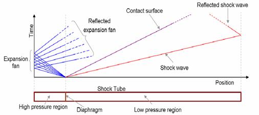
Fig. 35.3. Space time diagram for a typical shock tube