35.1 Shock Tube
The shock tube is a simple duct closed at both ends. A diaphragm divides this duct into two compartments called as driver and driven sections. Schemtic of the shock tube is as shown in Fig. 34]5.1. Driver section of the shock tube is the high pressure section which is supplied by the high pressure gas from the reservior. Driven section of the shock tube is the low pressure section which contains the low pressure driven gas. These two sections are separated by a metal diaphragm.
35.2 Working of Shock Tube
Typical shock tube experimental set up is as shown in Fig. 35.1. A high pressure driver gas reservoir is connected with the driver section. However a vacuum pump is connected to the driven section to arrive at the accurate driven section pressure. Pressure sensors are generally mounted along the driven tube for pressure measurement. Threse pressure sensors aare connected to the data acqusition system.
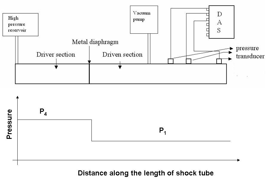
Fig. 35.1. Schematic of the shock tube.
Operating steps for this set up are as follows.
1. Set the metal diaphragm between the driver and driven section.
2. Fill the driven gas in the driven section from the driven gas reserior. This step is not required for case of air as the driven gas.
3. Set the required pressure in the driven section using vacuum pump.
4. Start filling the driver gas (say helium) in the driver section from the high pressure reservoir.
Metal diaphragm bursts at a paricular driver and driven gas pressure difference. Dynamics of operation of shock tube after diaphragm burst is shown ins steps in the following Fig. 35.2.
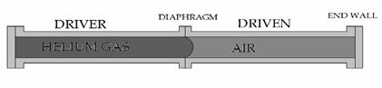
(a) On set of diaphragm burst.
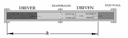
(b) Propagartion of shock, expansion and contact surface in the shock tube
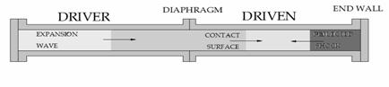
(c) Reflection of shock and expansion from the ends of the shock tube
Fig. 35.2 Motion of various waves inside the shock tube