22.2 Ineraction of shocks of differet family
Now consider the same S/S interaction problem for shocks of different strengths. As shown in Fig. 22.3 wedge angles and hence the flow deflection angles are shown different to imitate the two different shock strength for S/S interaction understanding.,/
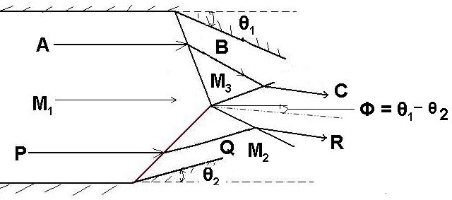
Fig, 22.3. Typical example of S/S interaction of shocks of different families and dfiferent strength.
Here the wedge angles are θ1 and θ2 for top wedge and bottom wedge respectively, where θ1 > θ2 in magnitude. Similar to the earlier situation, the top wedge is responsible for right running shock wave while bottom wedge is responsible for left running shock wave. Consider the streamlines ABC passing through the right running shock originated from top wedge and streamline PQR passing through the left running shock originated from bottom wedge. Initial deflection acquired by both the streamlines will be different in this case since the flow delfection angles are different. Flow deflection angles and corresponding pressures at point B and Q are shown using the P-θ diagram in Fig. 22.4. Here we can clearly see that points A & P are identical due to the fact that both the points belong to the region upstream of shocks.
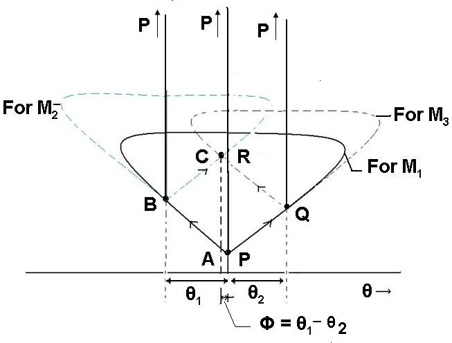
Fig, 22.4. Pressure deflection diagram for S/S interaction of shocks of different families and dfiferent strength.
In this situation, streamline ABC gets negative deflection of higher magnitude at points B in comparison with the defelction of streamline PQR at point Q. Due to higher strength of the right running shock, pressure at point B will be more than that of point Q. Therefore unlike earlier situation, all the flow properties will be different downstream of the first shocks at B and Q. Suppose, both the shocks are weak enough to keep the flow supsonic in the region given by points B and Q of the streamlines. However, when both (right and left running) shocks intersect, we can see similar interaction from where two new shocks originate. The reason for presence of these two shocks is to make the flows (passing over top wedge and passing over bottom wedge) parallel to each other. Streamline ABC which has higher deflection, now passes through the left running shock but can not cancel the earlier deflection completely. Hence, the part of the flow passed from the top wedge ratains certain negetaive deflection in the region of point C. At the same time, the part of the flow passing from the bottom wedge, which has positive deflection with respective passes though the right running shock which intern cancels its positive deflection and induces negative deflection in the region of point R so that streamlines ABC and PQR become parallel to each other at the end of the interaction region. Hence the strength of the shock encountered by the streamline PQR while passing from Q to R is higher than the strength of the shock encountered by the streamline ABC while passing from B to C. The new entity which we can observe is the slip line (shown by dotted line) which originates from the point of intersection of the shocks. The main purpose of this line is to avoid mixing of two flows passing from two differnt shock patterns which have different entropies. However pressure and direction of velocity remains conserved across this line. Therefore the final points C and R shown in Fig. 22.4 portray finite amount of same deflection and pressure.