Step 1: Determine the desired view of the object, then draw the isometric axes. The best view appeases to be that when the object is viewed from the top (regular isometric). the object will be viewed from above and the axis will be as shown in Fig. A.
Step2. Draw the isometric axes as shown in step 1.
Step 3. Construct the top isometric plane using the W and D dimensions.
Step 4. Construct the right side isometric plane using D and H dimensions.
Step 5. Locate the slot across the top plane by measuring distances E, F, and G along isometric lines.
Step 6. Locate the endpoints of the oblique plane in the top plane by locating distances A, B, C, and D along the lines created for the slot in Step 5. Label the end-point of line A as 5, line B as 1, line C as 4, and lire D as 7. Locate distance H along the vertical isometric line in the front plane of the isometric box and label the end point 6. Then locate distance I along the isometric line in the profile isometric plane and label the end point 8. Connect endpoints 5-7 and endpoint 6-8. Connect points 5-6 and 7-8.
Step 7. Draw a line from point 4 parallel to line 7. This new line should intersect at point 3. Locate point 2 by drawing a line from point 3 parallel to line 4 and equal in length to the distance between points 1 and 4. Draw a line from point 1 parallel to line 5-6. This new line should intersect point 2.
Step 8. Darken lines 4-3, 3-2, and 2-1 to complete the isometric view of the object.
Isometric drawing of objects having irregular curved surfaces.
Irregular curves are drawn in isometric by constructing points along the curve in the multi-view drawing, locating those points in the isometric view, and then connecting the points using a drawing instrument such as a French curve. The multi-view drawing of the curve is divided into a number of segments by creating a grid of lines and reconstructing the grid in the isometric drawing. The more segments chosen, the longer the curve takes to draw, but the curve will be more accurately represented in the isometric view.
Example 5. To draw the isometric view of the object having Irregular curve shown in figure 6.
The step wise procedure of drawing isometric view of object is shown in figure 6.
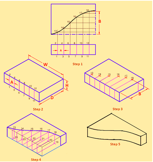
Figure 6. Isometric view of an object havingirregular curved shape.
Step 1. On the front view of the multi-view drawing of the curve, construct parallel lines and label the points 1, 2, 3, ….., 12. Project these lines into the top view until they intersect the curve. Label these points of intersection 13, 14, 15, …18, as shown in the Figure. Draw horizontal lines through each point of intersection, to create a grid of lines.
Step 2. Use the W, H, and D dimensions from the multi-view drawing to create the isometric box for the curve. Along the front face of the isometric box, transfer dimension A to locate and draw lines 1-2, 3-4, 5-6, 7-8, 9-10, and 11-12.
Step 3. From points 2, 4, 6, 8, 10, and 12, draw isometric lines on the top face parallel to the D line. Measure the horizontal spacing between each of the grid lines in the top multi-view as shown for dimension B, and transfer those distances along isometric lines. parallel to the W line. The intersections of the lines will locate points 13-18.
Step 4. Draw the curve through points 13-18, using an irregular curve. From points 13-18, drop vertical isometric lines equal to dimension H. From points 1, 3, 5, 7, 9, and 11 construct isometric lines across the bottom face to intersect with the vertical lines dropped from the top face to locate points 19-24. Connect points 19-24 with an irregular curve.
Step 5. Erase or lighten all construction lines to complete the view