Example 2. Drawing Non-Isometric Lines
Non-isometric lines will be the edges of inclined or oblique planes of an object as represented in a multi-view drawing. It is not possible to measure the length or angle from an inclined or oblique line in a multi-view drawing and then transferring these distances to draw the line in an isometric drawing. Instead, non-isometric lines must be drawn by locating the two end points of the lines on isometric lines and then connecting these end points with a line. The process used is called offset measurement, which is a method of locating one point by projecting another point. Figure 3. Illustrates the step wise procedure of drawing the isometric view of an object having inclined or oblique planes.
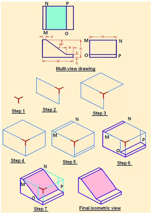
Figure 3. Step wise procedure of drawing the isometric view of the object having non-isometric planes.
Step 1. Determine the desired view of the object, then draw the isometric axes. Here it is preferred that the object be viewed from above, and the axis shown in Figure A is used.
Step 2. Construct the front isometric plane using W and H dimensions.
Step 3. Construct the top isometric plane using the W and D dimensions.
Step 4. Construct the right side isometric plane using D and H dimensions.
Step 5. Transfer the distances for A and C from the multi-view drawing to the top and right side isometric rectangles. Draw line MN across the top face of the isometric box. Draw an isometric construction line from the endpoint marked for distance C. This projects the distance C along the width of the box.
Step 6. Along these isometric construction lines, mark off the distance B, thus locating points O and P. Connect points OP.
Step 7. Connect points MO and NP to draw the non-isometric lines.