The orthographic projections of the plane, shown in figure 4(c) can be obtained be the following steps.
Draw XY and X1Y1 lines and mark HP, VP and left PP.
Draw the square abcd in true shape to represent the top view at any convenient distance below the XY line.
In the front view, the square lamina appears as a line parallel to the XY line. Obtain the front view as a line a'(d')b'(c') by projecting from the top view, parallel to the XY line at any convenient distance above it. In the front view, the rear corners D and C coincide with the front corners A and B, hence d' and c' are indicated within brackets.
Since the square lamina is also perpendicular to left PP, the right view projected on it will also be a line perpendicular to X1Y1 line. Project the right view as explained in the previous case. In right view, the corners A and D coincide with the corners B and C respectively, hence (a') and (d'), are indicated within brackets.
C) Plane parallel to PP and perpendicular to both HP and VP
A pentagon lamina (plane surface) is placed in the first quadrant with its surface is parallel to left PP and perpendicular to both VP and HP.
Figure 5 (a) shows the views of the object when projected on to the three planes. Side view is shown as a”b”c’’d”e”, the front view as b’(c’)a’(d’)e’ and the top view as a(b)e(c)d .Since the plane is parallel to the PP, its side view a”b”c’’d”e” will be in its true shape. Since the plane is perpendicular to VP and HP, its front and side views will be projected as lines.
After projecting the pentagon lamina on VP, HP and PP, both HP and PP are rotated about XY and X1Y1 lines , as shown in figure 5(b), till they lie in-plane with that of VP.
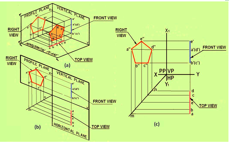
Figure 5 Projections of a pentagonal lamina with its surface parallel to PP and perpendicular to HP and VP.