Since the triangular lamina is also perpendicular to left PP, the right view will be a line parallel to the X1Y1 line. To project the right view, draw a 45° line at the point of intersection of the XY and X1Y1 lines.
Draw the horizontal projector through the corner a in the top view to cut the 45° line at m. Through m draw a vertical projector. From the corners c' and a' in the front view draw the horizontal projectors to cut the vertical projector drawn through m at c’’ and b’’. In the right view the corner A coincides with B and hence is invisible.
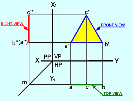
Figure 3. Orthographic projections of the lamina ABC
B) Plane parallel to HP and perpendicular to both VP and PP
A square lamina (plane surface) is placed in the first quadrant with its surface parallel to HP and perpendicular to both VP and left PP. Figure 4 (a) shows the views of the object when projected on to the three planes. Top view is shown as abcd, the front view as a’(d’)b’(c’) and the side view as b”(a”)c”(d”). Since the plane is parallel to the HP, its top view abcd will be in its true shape. Since the plane is perpendicular to VP and PP, its front and side views will be lines a’(d’)b’(c’) and b”(a”)c”(d”) respectively.
After projecting the square lamina on VP, HP and PP, both HP and PP are rotated about XY and X1Y1 lines , as shown in figure 4(b) , till they lie in-plane with that of VP.
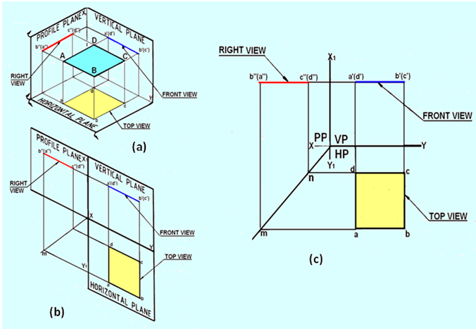
Figure 4. Projections of the lamina with its surface parallel to HO and perpendicular to both VP and PP.