HP is rotated by 90 degree to bring it in plane of VP (figure 4(a) . Subsequently, the AVP is rotated about the X1Y1 line (figure 4(b), such that it becomes in-plane with that of both HP and VP.
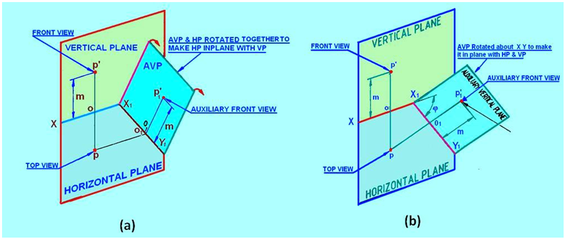
Figure 4. The rotation of (a) HP and (b) AVP to make HP and AVP in plane with VP.
The orthographic projections (projections of point P on HP, VP and AVP) of point P can be obtained be the following steps.
Draw the XY line and mark p and p', the top and front views of the point P. Since AVP is inclined at Φ to VP, draw the X1Y1 line inclined at Φ to the XY line at any convenient distance from p. Since point P is at a height m above HP, the auxiliary front view p1' will also be at a height m above the X1Y1 line. Therefore, mark P1’ by measuring o1p1’=op’ = m on the projector drawn from p perpendicular to the X1Y1 line.
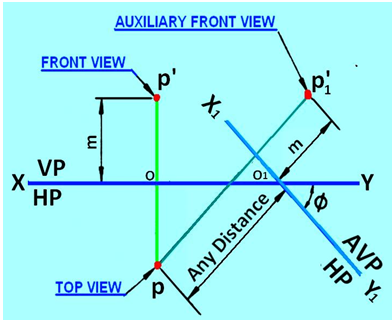
Figure 5. Orthographic projection of the point P by Auxiliary projection method.