Auxiliary Vertical Plane (AVP)
An AVP is placed in the first quadrant with its surface perpendicular to HP and inclined at Φ to VP. The object is assumed to be placed in the space in between HP, VP and AVP. The AVP intersects HP along the X1Y1 line. The direction of sight to project the auxiliary front view will be normal to AVP. The position of the auxiliary vertical plane w.r.t HP and VP is shown in figure 1.
After obtaining the top view, front view and auxiliary front view on HP, VP and AVP, the HP, with the AVP being held perpendicular to it, is rotated so as to be in-plane with that of VP, and then the AVP is rotated about the X1Y1 line so as to be in plane with that of already rotated HP.
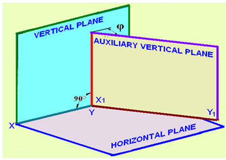
Figure 1. The position of the auxiliary vertical plane w.r.t HP and VP
Auxiliary Inclined Plane (AIP)
AIP is placed in the first quadrant with its surface perpendicular to VP and inclined at q to HP. The object is to be placed in the space between HP, VP and AIP. The AIP intersects the VP along the X1Y1 line. The direction of sight to project the auxiliary top view will be normal to the AIP. The position of the AIP w.r.t HP and VP is shown in figure 2.
After obtaining the top view, front view and auxiliary top view on HP, VP and AIP, HP is rotated about the XY line independently (detaching the AIP from HP). The AIP is then rotated about X1Y1 line independently so as to be in-planewith that of VP.
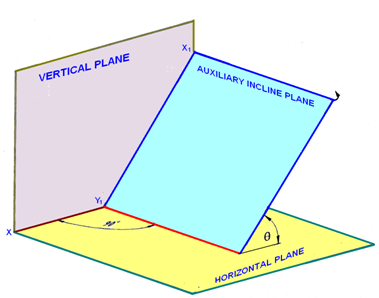
Figure 2. The position of the AIP w.r.t HP and VP