| 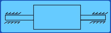
Fig 3.2.8 A Case of Dynamic Unbalance Consider the rotor shown in Fig. 3.2.8. It is easily observed that mass distribution cannot be approximately confined to just one plane. So unbalance masses and hence unbalance forces are in general present all along the length of the rotor. Such a case is known as dynamic unbalance.
The fundamental difference between static and dynamic unbalance needs to be clearly appreciated.
When a rotor as shown in Fig. 3.2.8 is mounted on a knife edge and allowed to oscillate freely, it too may come to rest in one particular position all the time the position corresponding to the resultant unbalance mass (centre of gravity) vertically below the knife edge. We could, like earlier, mount an appropriate balance mass exactly 1800 opposite to this position. It would then have no preferred position of rest when mounted on a knife-edge. Thus effective center of gravity lies on the axis.
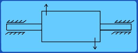
Fig 3.2.9 Example of unbalance masses leading to unbalance force that for a resultant couple because of axial.
However, when mounted in bearings and driven by a motor etc., it could still wobble due to the unbalanced moments of these forces as shown in Fig. 3.2.9. This becomes apparent only when the rotor is driven to rotate and hence the name dynamic unbalance. Thus it is not, in general, sufficient to do just static balance but achieving good dynamic balance is more difficult. We will discuss one important method of achieving dynamic balance in the next lecture.
|