| A rotor can in general have two types of unbalance viz., static and dynamic. It is of course to be appreciated that practical systems will all have dynamic unbalance only and considering it as static unbalance is a good-enough approximation for some cases.
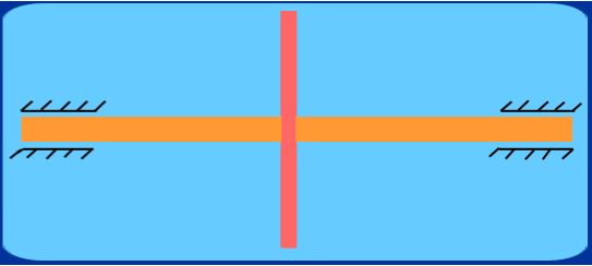
Fig 2.2.6 A thin Rotor Disc - Illustration of Static Unbalance
If the rotor is thin enough (longitudinally) as shown in Fig. 2.2.6, the unbalance force can be assumed to be confined to one plane (the plane of the disc). Such a case is known as static unbalance. Such a system when mounted on a knife-edge as shown in Fig. 2.2.7, will always come to rest in one position only where the centre of gravity comes vertically below the knife-edge point. Thus in order to balance out, all we need to do is to attach an appropriate balancing mass exactly 1800 opposite to this position.
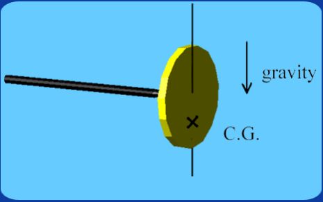
Fig 2.2.7 Thin Rotor on a knife edge - Illustration of Static Unbalance
Thus we first mount the disc on a knife edge and allow it to freely oscillate. Mark the position when it comes to rest. Choose a radial location (1800 opposite to this position) where we can conveniently attach a balancing mass. By trial and error the balancing mass can be found out. When perfectly balanced, the disc will exhibit no particular preferred position of rest. Also when the disc is driven to rotate by a motor etc., there will be no centrifugal forces felt on the system (for example, at the bearings). Thus the condition for static balance is simply that the effective centre of gravity lie on the axis.
|