Module 2 : Dynamics of Rotating Bodies; Unbalance Effects and Balancing of Inertia Forces; Field Balancing and Balancing Machines.
Lecture 1 : Concept of unbalance; effect of unbalance
From Fig. 2.1.3 it is observed that any eccentricity in the system leads to unbalanced forces and when frequencies match
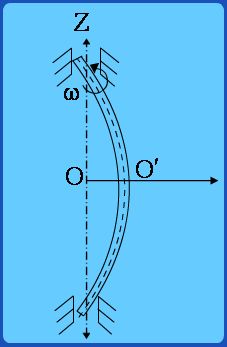
, this could lead to excessive deflections. It is to be observed that because of these forces, the shaft centerline is pulled away from line of bearings and the axis of rotation is thus bent. Please see Fig. 2.1.4. The system continues to rotate with a certain fixed deformed shape, the amount of deflection being given by equation(2.1.2).
Figure 2.1.4
When the speed of rotation of the shaft about its axis and the speed of rotation of the plane containing the bent shaft about the line of bearings is the same, it is known as “synchronous whirl”. In a synchronous whirl, Fig. 2.1.5 shows the side-view of the deformed rotor-shaft system at four different positions in one rotation. Thus the “heavier” fibers (indicated in the figure by the shaded portion) always remain outermost and thus in tension and the inner fibers are always in compression. Thus there is NO cyclic variation of stress from tension-compression for any given fiber. Thus synchronous whirl could lead to excessive amplitudes and possible failure but NOT to fatigue due to alternating stresses.
Fig 2.1.5 Position of Rotor-Disk at 0°, 90°, 180°, 270° in one rotation

 , this could lead to excessive deflections. It is to be observed that because of these forces, the shaft centerline is pulled away from line of bearings and the axis of rotation is thus bent. Please see Fig. 2.1.4. The system continues to rotate with a certain fixed deformed shape, the amount of deflection being given by equation(2.1.2).