Module 2   :  Dynamics of Rotating Bodies; Unbalance Effects and Balancing of Inertia  Forces
Lecture 1 :   Concept of unbalance; effect of unbalance
 

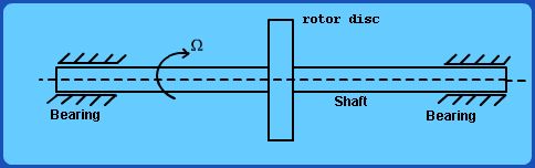
Consider a shaft mounted in its bearings as shown in Fig. 2.1.1


Fig 2.1.1 A simple Rotor


In the idealized situation shown in the figure, the shaft may be assumed mass-less and the rotor is representative of a thin disc with several blades attached around its circumference (such as in a single stage of turbo-machine). The armature of a typical motor can also be represented in this fashion.


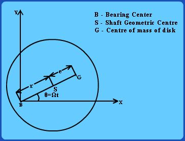
It is easy to see that the center of mass of the rotor disc may or may not lie on the geometric axis of the shaft in its bearings. Consider the side-view of the system as shown in Fig. 2.1.2 below. If the center of mass is NOT on the axis of rotation (i.e., the system is “eccentric”), then as the shaft rotates, a centrifugal force will be set-up. The shaft will then be bent away from the line of bearings.


Fig 2.1.2 Side View of The Rotor


2