|
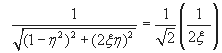
Thus we see that the peak amplitude near resonanceis limited purely by the damping present in the system. The lower the damping in the system, the higher the peak amplitude and the sharper the peak. Thus one can guess the extent of damping in a system by merely looking at the dynamic response curves as depicted in Fig. 9.1.4. From the value of vibration amplitude as given by equation (9.1.15) one can think of a method of experimentally determining the damping coefficient viz., measure the response at this condition and use eqn (9.1.15) to estimate the damping factor. However, another easy method of determining damping is commonly employed, which is known as the half-power-point method. When the magnification factor is 0.707 times the peak magnification factor i.e.,
 times , the corresponding frequency values on either side of resonance are given by (see Fig.9.1.5) |
|
|
(11.1.17) |
| |
|
(11.1.18) |
| |
|
(11.1.19) |
| |
Usually, 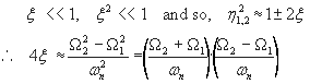 |
(11.1.20) |
| |
|
(11.1.21) |
| |
This is an effective method of determining the damping coefficient in a system using a forced vibration test.Logarithmic decrement is another effective technoque and is based on free vibration test. |
| |
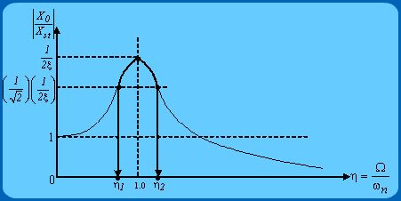 Figure 9.1.5 |
| |
|
|






