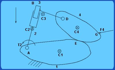
Consider the mechanism shown in fig. 1.6. It is a 4 link, 2 degree of freedom mechanism with two revolute joints, one prismatic joint, and one cam-follower joint which allows sliding. The link numbered 1 is the frame. It has a revolute joint A with link 2 and a cam-follower joint with link 4, with the contact being at E . Links 2 and 3 are connected by a prismatic joint, while links 3 and 4 are connected by a revolute joint D . The point B is on link 3. The centers of mass of link i is denoted by C i . Note that the center of mass of link 3 is outside the physical bounds of the link, a possibility with links with concave portions in their profile. A torque _ 2 acts on link 2, while a force F 4 acts on link 4 at point G as shown. The direction of gravity is as shown in figure.
|