Section III: Equal Area Criterion
The real power transmitted over a lossless line is given by (9.4). Now consider the situation in which the synchronous machine is operating in steady state delivering a power Pe equal to Pm when there is a fault occurs in the system. Opening up of the circuit breakers in the faulted section subsequently clears the fault. The circuit breakers take about 5/6 cycles to open and the subsequent post-fault transient last for another few cycles. The input power, on the other hand, is supplied by a prime mover that is usually driven by a steam turbine. The time constant of the turbine mass system is of the order of few seconds, while the electrical system time constant is in milliseconds. Therefore, for all practical purpose, the mechanical power is remains constant during this period when the electrical transients occur. The transient stability study therefore concentrates on the ability of the power system to recover from the fault and deliver the constant power Pm with a possible new load angle δ .
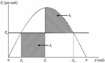
Consider the power angle curve shown in Fig. 9.3. Suppose the system of Fig. 9.1 is operating in the steady state delivering a power of Pm at an angle of δ0 when due to malfunction of the line, circuit breakers open reducing the real power transferred to zero. Since Pm remains constant, the accelerating power Pa becomes equal to Pm . The difference in the power gives rise to the rate of change of stored kinetic energy in the rotor masses. Thus the rotor will accelerate under the constant influence of non-zero accelerating power and hence the load angle will increase. Now suppose the circuit breaker re-closes at an angle δc. The power will then revert back to the normal operating curve. At that point, the electrical power will be more than the mechanical power and the accelerating power will be negative. This will cause the machine decelerate. However, due to the inertia of the rotor masses, the load angle will still keep on increasing. The increase in this angle may eventually stop and the rotor may start decelerating, otherwise the system will lose synchronism.
Note that
Fig. 9.3 Power-angle curve for equal area criterion.
Hence multiplying both sides of (9.14) by  and rearranging we get and rearranging we get
Multiplying both sides of the above equation by dt and then integrating between two arbitrary angles δ0 and δc we get

|
(9.15) |
Now suppose the generator is at rest at δ0. We then have dδ / dt = 0. Once a fault occurs, the machine starts accelerating. Once the fault is cleared, the machine keeps on accelerating before it reaches its peak at δc , at which point we again have dδ / dt = 0. Thus the area of accelerating is given from (9.15) as

|
(9.16) |
In a similar way, we can define the area of deceleration. In Fig. 9.3, the area of acceleration is given by A1 while the area of deceleration is given by A2 . This is given by

|
(9.17) |
Contd... |