...Contd... Equal Area Criterion
Now consider the case when the line is reclosed at δc such that the area of acceleration is larger than the area of deceleration, i.e., A1 > A2 . The generator load angle will then cross the point δm , beyond which the electrical power will be less than the mechanical power forcing the accelerating power to be positive. The generator will therefore start accelerating before is slows down completely and will eventually become unstable. If, on the other hand, A1 < A2 , i.e., the decelerating area is larger than the accelerating area, the machine will decelerate completely before accelerating again. The rotor inertia will force the subsequent acceleration and deceleration areas to be smaller than the first ones and the machine will eventually attain the steady state. If the two areas are equal, i.e., A1 = A2 , then the accelerating area is equal to decelerating area and this is defines the boundary of the stability limit. The clearing angle δc for this mode is called the Critical Clearing Angle and is denoted by δcr. We then get from Fig. 9.3 by substituting δc = δcr

|
(9.18) |
We can calculate the critical clearing angle from the ab move equation. Since the critical clearing angle depends on the equality of the areas, this is called the equal area criterion.
Example 9.3:
Consider the system of Example 9.1. Let us assume that the system is operating with Pm = Pe = 0.9 per unit when a circuit breaker opens inadvertently isolating the generator from the infinite bus. During this period the real power transferred becomes zero. From Example 9.1 we have calculated δ0 = 23.96 ° = 0.4182 rad and the maximum power transferred as
 per unit per unit
|
|
We have to find the critical clearing angle.
From (9.15) the accelerating area is computed as by note that Pe = 0 during this time. This is then given by
To calculate the decelerating area we note that δm = π - 0.4182 = 2.7234 rad. This area is computed by noting that Pe = 2.2164 sin(δ ) during this time. Therefore
Equating A1 = A2 and rearranging we get
|
Now a frequently asked question is what does the critical clearing angle mean?
Since we are interested in finding out the maximum time that the circuit breakers may take for opening, we should be more concerned about the critical clearing time rather than clearing angle. Furthermore, notice that the clearing angle is independent of the generalized inertia constant H . Hence we can comment that the critical clearing angle in this case is true for any generator that has a d-axis transient reactance of 0.20 per unit. The critical clearing time, however, is dependent on H and will vary as this parameter varies.
To obtain a description for the critical clearing time, let us consider the period during which the fault occurs. We then have Pe = 0. We can therefore write from

|
(9.19) |
Integrating the above equation with the initial acceleration being zero we get
Further integration will lead to
Replacing δ by δcr and t by tcr in the above equation, we get the critical clearing time as

|
(9.20) |
Example 9.4:
In Example 9.2, let us choose the system frequency as 50 Hz such that ωs is 100π. Also let us choose H as 4 MJ/MVA. Then with δcr being 1.5486 rad, δ0 being 0.4182 rad and Pm being 0.9 per unit, we get the following critical clearing time from (9.20)
 s s
|
|
|
To illustrate the response of the load angle δ , the swing equation is simulated in MATLAB. The swing equation of (9.14) is then expressed as

|
(9.21) |
where Δωr is the deviation for the rotor speed from the synchronous speed ωs . It is to be noted that the swing equation of (9.21) does not contain any damping. Usually a damping term, that is proportional to the machine speed Δωr, is added with the accelerating power. Without the damping the load angle will exhibit a sustained oscillation even when the system remains stable when the fault cleared within the critical clearing time.
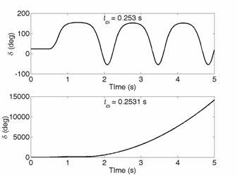
Fig. 9.4 Stable and unstable system response as a function of clearing time.
Fig. 9.4 depicts the response of the load angle δ for two different values of load angle. It is assumed that the fault occurs at 0.5 s when the system is operating in the steady state delivering 0.9 per unit power. The load angle during this time is constant at 23.96° . The load angle remains stable, albeit the sustained oscillation when the clearing time tcl is 0.253 s. The clearing angle during this time is 88.72° . The system however becomes unstable when the clearing time 0.2531s and the load angle increases asymptotically. The clearing time in this case is 88.77° . This is called the Loss of Synchronism. It is to be noted that such increase in the load angle is not permissible and the protection device will isolate the generator from the system.
The clearing time of (8.20) is derived based on the assumption that the electrical power Pe becomes zero during the fault as in (8.19). This need not be the case always. In that even we have to resort to finding the clearing time using the numerical integration of the swing equation. See example 9.5 to illustrates the point.
Example 9.5
|