Improving Power-Angle Characteristics
The apparent power supplied by the source is given by
 |
(10.7) |
Similarly the apparent power delivered at the receiving end is
 |
(10.8) |
Hence the real power transmitted over the line is given by
 |
(10.9) |
Combining (10.6)-(10.8), we find the reactive power consumed by the line as
 |
(10.10) |
The power-angle characteristics of the shunt compensated line are shown in Fig. 10.3. In this figure Pmax = V2/X is chosen as the power base.
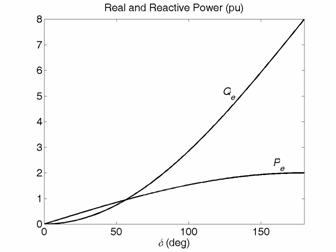
Fig. 10.3 Power-angle characteristics of ideal shunt compensated line.
Fig. 10.3 depicts Pe - δ and QQ - δ characteristics. It can be seen from fig 10.4 that for a real power transfer of 1 per unit, a reactive power injection of roughly 0.5359 per unit will be required from the shunt compensator if the midpoint voltage is regulated as per (10.1). Similarly for increasing the real power transmitted to 2 per unit, the shunt compensator has to inject 4 per unit of reactive power. This will obviously increase the device rating and may not be practical. Therefore power transfer enhancement using midpoint shunt compensation may not be feasible from the device rating point of view.
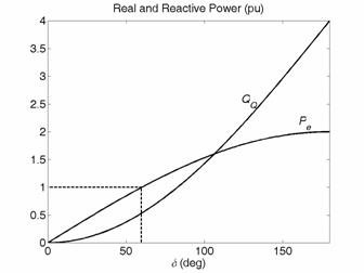
Fig. 10.4 Variations in transmitted real power and reactive power injection by the shunt compensator with load angle for perfect midpoint voltage regulation.
Let us now relax the condition that the midpoint voltage is regulated to 1.0 per unit. We then obtain some very interesting plots as shown in Fig. 10.5. In this figure, the x-axis shows the reactive power available from the shunt device, while the y-axis shows the maximum power that can be transferred over the line without violating the voltage constraint. There are three different P-Q relationships given for three midpoint voltage constraints. For a reactive power injection of 0.5 per unit, the power transfer can be increased from about 0.97 per unit to 1.17 per unit by lowering the midpoint voltage to 0.9 per unit. For a reactive power injection greater than 2.0 per unit, the best power transfer capability is obtained for VM = 1.0 per unit. Thus there will be no benefit in reducing the voltage constraint when the shunt device is capable of injecting a large amount of reactive power. In practice, the level to which the midpoint voltage can be regulated depends on the rating of the installed shunt device as well the power being transferred.
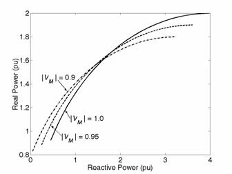
Fig. 10.5 Power transfer versus shunt reactive injection under midpoint voltage constraint.
|