Improving Voltage Profile
Let the sending and receiving voltages be given by  and and  respectively. The ideal shunt compensator is expected to regulate the midpoint voltage to respectively. The ideal shunt compensator is expected to regulate the midpoint voltage to
 |
(10.1) |
against any variation in the compensator current. The voltage current characteristic of the compensator is shown in Fig. 10.2. This ideal behavior however is not feasible in practical systems where we get a slight droop in the voltage characteristic. This will be discussed later.
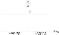
Fig. 10.2 Voltage-current characteristic of an ideal shunt compensator.
Under the assumption that the shunt compensator regulates the midpoint voltage tightly as given by (10.1), we can write the following expressions for the sending and receiving end currents
 |
(10.2) |
 |
(10.3) |
Again from Fig. 10.1 we write
 |
(10.4) |
Combing (10.2)-(10.4) and solving we get
 |
(10.5) |
We thus have to generate a current that is in phase with the midpoint voltage and has a magnitude of (4V / XL ){1 - cos( δ /2)}. The apparent power injected by the shunt compensator to the ac bus is then
 |
(10.6) |
Since the real part of the injected power is zero, we conclude that the ideal shunt compensator injects only reactive power to the ac system and no real power. |