...Contd from previous slide...
The equivalent circuit is shown in Fig. 1.16. Let the current ia lag the internal emf ea by θa . The stator currents are then
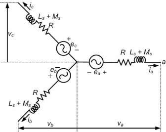
Fig. 1.16 Three-phase equivalent circuit of a synchronous generator.
The single-phase equivalent circuit is shown in Fig. 1.17. The phase angle θabetween eaand ia is rather difficult to measure under load as ea is the no load voltage. To avoid this, we define the phase angle between νa and ia to be θ . We assume that ea leads νaby δ . Therefore we can write
 |
(1.112) |
Then the voltages and currents shown in Fig. 1.17 are given as
Equations (1.113) to (1.115) imply that
 |
(1.116) |
The synchronous impedance is then defined as
 |
(1.117) |
The terminal voltage equation is then
 |
(1.118) |
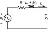
Fig. 1.17 Single-phase equivalent circuit of a synchronous generator.
|