Section III Synchronous Machine Model
The schematic diagram of a synchronous generator is shown in Fig. 1.15. This contains three stator windings that are spatially distributed. It is assumed that the windings are wye-connected. The winding currents are denoted by ia , ib and ic. The rotor contains the field winding the current through which is denoted by if . The field winding is aligned with the so-called direct ( d ) axis. We also define a quadrature ( q ) axis that leads the d -axis by 90°. The angle between the d-axis and the a-phase of the stator winding is denoted by θd.
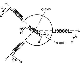
Fig. 1.15 Schematic diagram of a synchronous generator.
Let the self-inductance of the stator windings be denoted by Laa, Lbb, Lcc such that
 |
(1.80) |
and the mutual inductance between the windings be denoted as
 |
(1.81) |
The mutual inductances between the field coil and the stator windings vary as a function of θd and are given by
The self-inductance of the field coil is denoted by Lff.
The flux linkage equations are then given by

|
(1.85) |

|
(1.86) |
|
(1.87) |
|
(1.88) |
For balanced operation we have
Hence the flux linkage equations for the stator windings (1.85) to (1.87) can be modified as
For steady state operation we can assume
 |
(1.92) |
Also assuming that the rotor rotates at synchronous speed ωs we obtain the following two equations

|
(1.93) |

|
(1.94) |
where θd0 is the initial position of the field winding with respect to the phase-a of the stator winding at time t = 0. The mutual inductance of the field winding with all the three stator windings will vary as a function of θd, i.e.,
Substituting (1.92), (1.94), (1.95), (1.96) and (1.97) in (1.89) to (1.91) we get
Since we assume balanced operation, we need to treat only one phase. Let the armature resistance of the generator be R . The generator terminal voltage is given by
 |
(1.101) |
where the negative sign is used for generating mode of operation in which the current leaves the terminal. Substituting (1.98) in (1.101) we get
 |
(1.102) |
The last term of (1.102) is the internal emf ea that is given by
 |
(1.103) |
where the rms magnitude Ei is proportional to the field current
 |
(1.104) |
Since θd0 is the position of the d -axis at time t = 0, we define the position of the q -axis at that instant as
 |
(1.105) |
Therefore (1.94) can be rewritten as
 |
(1.106) |
Substituting (1.105) in (1.103) we get
 |
(1.107) |
Hence (1.102) can be written as
 |
(1.108) |
Contd.. |