Section IV: Transformer Model
The equivalent circuit of a single-phase transformer is shown in Fig. 1.18. In this the primary voltage and currents are denoted by V1 and V2 respectively. The current entering the primary terminals is I1. The core loss component is represented by Rcwhile the magnetizing reactance is denoted by Xm . The leakage inductance of the transformer is denoted by Xeqand Req is transformer winding resistance. It is to be noted that all the quantities are referred to the primary side. The turns ratio of the transformer is given by N1 : N2 .
The impedance of the shunt branch is much larger compared to that of the series branch. Therefore we neglect Rcand Xm. Again of the series parameters, Reqis much smaller than Xeq. We can therefore neglect the series impedance. Therefore the transformer can be represented by the leakage reactance Xeq. The single-phase transformer equivalent circuit, when referred to the primary side, is as shown is Fig. 1.19 (a). The equivalent circuit, when referred to the secondary side, is shown in Fig. 1.19 (b) where a = N1 / N2 . 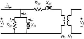
Fig. 1.18 Equivalent circuit of a single-phase transformer

Fig. 1.19 Simplified equivalent circuit of a single-phase transformer: (a) when referred to the primary side and (b) when referred to the secondary side. |