Capacitance of a Single-Phase Line
Consider the single-phase line consisting of two round conductors as shown in Fig. 1.5. The separation between the conductors is D . Let us assume that conductor 1 carries a charge of q1 C/m while conductor 2 carries a charge q2 C/m. The presence of the second conductor and the ground will disturb field of the first conductor. However we assume that the distance of separation between the conductors is much larger compared to the radius of the conductor and the height of the conductor is much larger than D for the ground to disturb the flux. Therefore the distortion is small and the charge is uniformly distributed on the surface of the conductor.
Assuming that the conductor 1 alone has the charge q1 , the voltage between the conductors is
 V V |
(1.61) |
Similarly if the conductor 2 alone has the charge q2 , the voltage between the conductors is
 V V |
|
The above equation implies that
 V V |
(1.62) |
From the principle of superposition we can write
 V V |
(1.63) |
For a single-phase line let us assume that q1 (= -q2 ) is equal to q . We therefore have
 V V |
(1.64) |
Assuming r1 = r2= r3, we can rewrite (1.64) as
 V V |
(1.65) |
Therefore from (1.57) the capacitance between the conductors is given by
 V F/m V F/m |
(1.66) |
The above equation gives the capacitance between two conductors. For the purpose of transmission line modeling, the capacitance is defined between the conductor and neutral. This is shown in Fig. 1.13. Therefore the value of the capacitance is given from Fig. 1.13 as
 F/m F/m |
(1.67) |
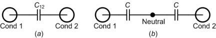
Fig. 1.13 (a) Capacitance between two conductors and (b) equivalent capacitance to ground. |