Capacitance of a Straight Conductor
Consider the round conductor shown in Fig. 1.11. The conductor has a radius of r and carries a charge of q coulombs. The capacitance C is the ratio of charge q of the conductor to the impressed voltage, i.e.,
 |
(1.57) |
The charge on the conductor gives rise to an electric field with radial flux lines where the total electric flux is equal to the charge on the conductor. By Gauss's law, the electric flux density at a cylinder of radius x when the conductor has a length of 1 m is
 C/m2 C/m2 |
(1.58) |
The electric filed intensity is defined as the ratio of electric flux density to the permittivity of the medium. Therefore
 V/m V/m |
(1.59) |
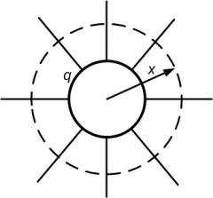
Fig. 1.11 Cylindrical conductor with radial flux lines.
Now consider the long straight conductor of Fig. 1.12 that is carrying a positive charge q C/m. Let two points P1 and P2 be located at distances D1 and D2 respectively from the center of the conductor. The conductor is an equipotential surface in which we can assume that the uniformly distributed charge is concentrated at the center of the conductor. The potential difference V12 between the points P1 and P2 is the work done in moving a unit of charge from P2 to P1 . Therefore the voltage drop between the two points can be computed by integrating the field intensity over a radial path between the equipotential surfaces, i.e.,
 V V |
(1.60) |
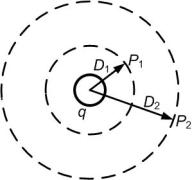
Fig. 1.12 Path of integration between two points external to a round straight conductor. |