Chandrapur Padghe HVDC link
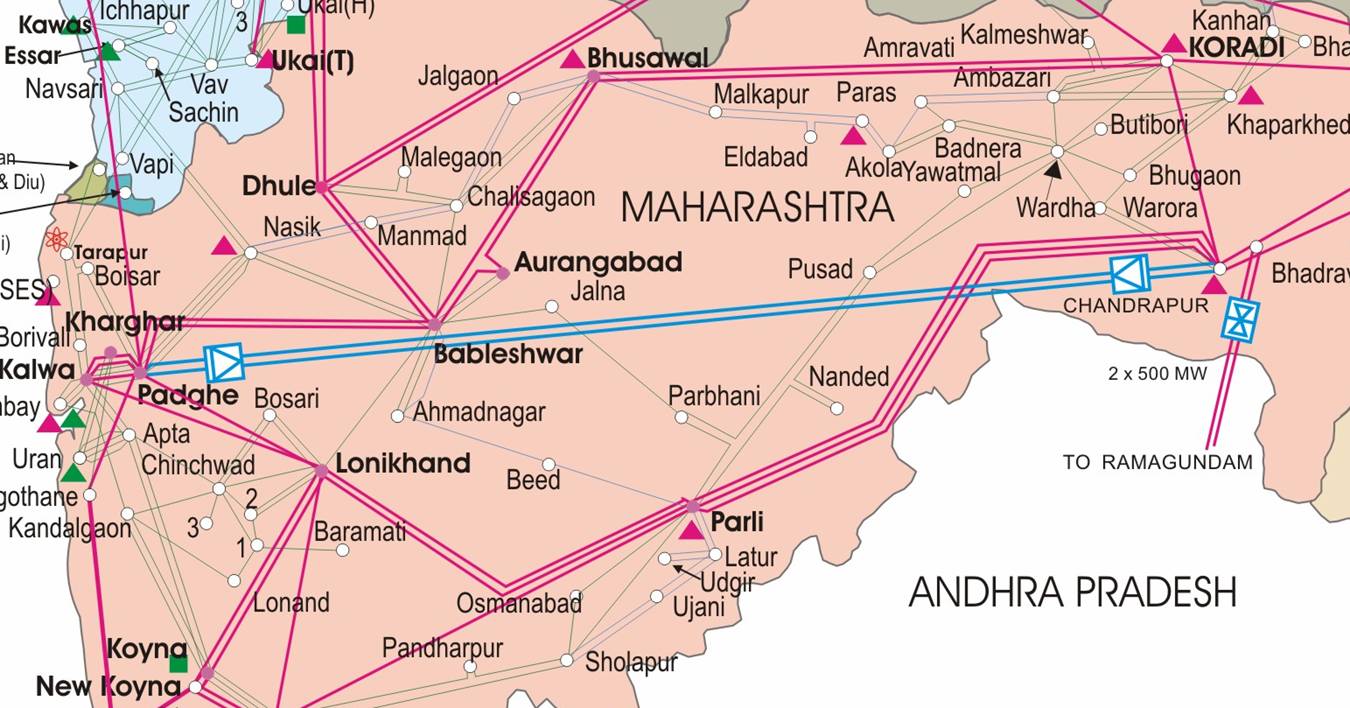
Maharashtra state, which is a part of the western regional grid of India, has most of its large generators in the eastern part of the state. The thermal power station at Chandrapur generates more than 2200 MW of power. However, most of the major loads lie in the western part of the state, i.e., in and around Mumbai, Nashik and Pune, which are at a distance of more than 600 km. Although 400 kV AC lines, are present they pose stability and voltage constraints due to the long distances involved. Therefore an HVDC link between Chandrapur and Padghe was planned and executed.
We have seen the power map of the western region of India. The figure below highlights the Maharashtra state grid. The 400 kV lines are in pink while the HVDC link is shown in blue. An asynchronous DC link between the Western and Southern region is also present (between Bhadrawati and Ramagundam).
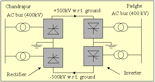
The Chandrapur -Padghe DC link is primarily meant for point to point bulk power transfer. The overall capacity of the link is 1500 MW and consists of two sets of converters at Chandrapur (rectifier end) and Padghe (inverter end). The voltage between the two lines which form the link is maintained at about 1000 kV. The voltage of each line with respect to the ground is about +/-500 kV. The link also allows for power flow in the ground for a short while if one conductor which forms the return path is unavailable.
The power flows are set as per the schedule decided by a system operator, and implemented by closed loop control of the firing angles of both the rectifier(Chandrapur) and inverter (Padge).
 |
Ratings of Link |
Power Transmission Capability (MW) |
Minimum Continuous Rating |
1500 |
| Nominal Rating |
1500 |
| 2 hours overload rating |
1650 |
| 5 second overload rating |
2000 |
| Rating under reduced DC voltage |
1000 |
Fast control possible with power electronics also allows for the additional capabilities:
a) In case degraded insulation conditions exist, power can be transmitted at slightly lower voltages (losses will increase though).
b) The link can reverse power flow in case the system conditions so demand.
c) The HVDC link can act like an asynchronous link in case the eastern and western part of the state are not in synchronism and power flow can be controlled to keep frequency at one end constant.
d) The reactive power absorbed at both rectifier and inverter can be increased if overvoltage conditions exist.
e) In case a parallel AC line (e.g., Chandrapur -Parli 400 kV line in the above figure) is tripped, it is possible to increase the power flow in the DC link to prevent instability or overload of other AC lines.
(Data obtained from "Operation, Maintainance and Protection Aspects of 1500 MW, +/- 500 kV Chandrapur-Padghe Bipole project", by R.S. Khandagale et al, Annual Workshop for Load Despatch Personnel and System Operators, Sept 2002, Mumbai) |


