|
The ITS Architecture provides a common framework for planning, defining, and
integrating intelligent transportation systems.
It specifies how the different ITS components would interact with each other to
help solving transportation problems.
It provides the transportation professionals to address their needs with wide
variety of options.
It identifies and describes various functions and assigns responsibilities to
various stake-holders of ITS.
The ITS architecture should be common and of specified standards throughout the
state or region so that it can address solution to several problems while
interacting with various agencies.
- Interoperability - The ITS architecture should be such that the
information collected, function implemented or any equipment installed be
interoperable by various agencies in different state and regions.
- Capable of sharing and exchanging information - The information by traffic
operations may be useful to the emergency services.
- Resource sharing - regional communication towers constructed by various
private agencies are required to be shared by ITS operations.
This is developed by US Department of Transportation to provide guidance and
co-ordinate all regions in deploying ITS.
It documents all information available and keep updating continuously.
The national architecture contains the following components:
A number of functions are needed to accomplish the user services.
These functional statements are called user services requirements.
For all the user services the requirements have been specified.
If any new function is added, new requirements are to be defined.
Table. 1 shows an illustration of user
service requirements for traffic control user service.
Table 1:
User service requirements for Traffic Control user service
| Traffic Control provides the capability to efficiently manage the movement of
traffic |
| on streets and highways.
Four functions are provided which are |
| (1) Traffic Flow Optimization, |
|---|
| (2) Traffic Surveillance, |
|---|
| (3) Control, and |
|---|
| (4) Provide Information. |
|---|
| This will also include control of network signal systems with integration of
freeway |
| control.
The specified User service requirements |
| (1) TC shall include a Traffic Flow Optimization function to provide
the capability |
|---|
| to optimize traffic flow. |
| (1.1) Traffic Flow Optimization shall employ control strategies that
seek to maximize |
|---|
| traffic-movement efficiency. |
| (1.2) Traffic Flow Optimization shall include a wide area optimization
capability, to |
|---|
| include several jurisdictions. |
| (1.2.1) Wide area optimization shall integrate the control of network
signal systems |
|---|
| with the control of freeways. |
| (1.2.2) Wide area optimization shall include features that provide
preferential |
|---|
| treatment for transit vehicles. |
| (2) TC shall include a Traffic Surveillance function. |
|---|
To accomplish user service requirements many functions or processes are needed.
The logical architecture defines a set of functions (or processes) and
information flows (or data flows) that respond to the user service requirements.
It describes the lower end interaction of different components of ITS.
Processes and data flows are grouped to form a particular functions.
These are represented graphically by data flow diagrams (DFDs).
Fig. 1 shows the interaction of Manage Traffic
process with other processes.
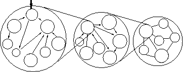
Each process is broken down into more sub processes.
The sub process is further broken into sub process which are called process
specifications (P-specs) lowest level.
These p specs are required to be performed to fulfill user services
requirements.
Fig. 2 shows process decomposition into
process specifications.
Figure 1:
High level ITS logical architecture
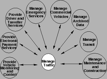 |
Figure 2:
Decomposition of process into P-specs
 |
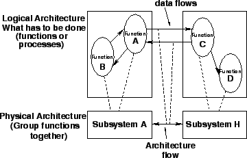
The functions from logical architecture that serve the same need are grouped
into sub systems.
With these subsystems a physical entity is developed to deliver functions.
The data flow of logical architecture are also combined to define interface
between subsystems.
Fig. 3 shows the functions A and B of logical
architecture assigned to subsystem A in physical architecture.
Both the architecture forms the core of ITS.
Figure 3:
Assigning function from logical to the physical architecture
 |
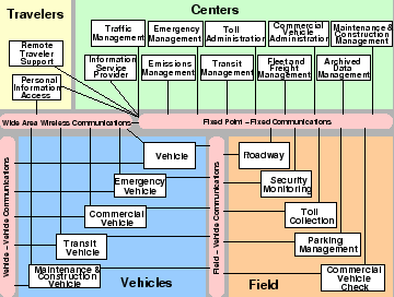
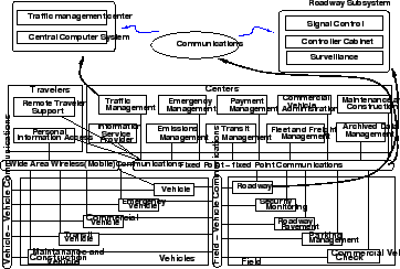
The physical architecture of ITS defines the physical subsystems and
architectural flows based on the logical architecture.
The 22 subsystems are broadly classified in four groups as centers, field,
vehicle, and travelers.
Fig. 4 shows the subsystems and
communications that comprise the national physical architecture.
The subsystem represent aggregation of functions that serve the same
transportation need and closely correspond to physical elements of
transportation management system.
Vehicle group consists of five different types of vehicles.
The traveler group represents different ways a traveler can access information
on the status of the transportation system.
There are four different types of communication systems.
- Fixed point to fixed point
- Wide area wireless
- Vehicle - vehicle communication
- Field - vehicle communication
Figure 4:
National ITS physical architecture showing subsystems and
communications
 |
Through the communication systems all the subsystems are interconnected and
transfer the required data.
Fig. 5 shows the communication between
traffic management subsystem and the roadway subsystem.
Traffic management subsystem is connected to communications which gets real time
information of the transportation system through roadway subsystem which
comprise of signal control, detectors, camera, VMS etc.
Figure 5:
Communications between subsystems of physical architecture
 |
In order to provide more deployment oriented perspective to the ITS architecture
an equipment package is developed.
In this similar functions of a particular subsystem are grouped together and
implemented by a package of hardware and software facilities.
As an example Table. 2 shows the TMC signal
control equipment package and its functional requirements.
Table 2:
TMC Signal control equipment package
| TMC Equipment package provides the capability for traffic managers to monitor |
| and manage the traffic flow at signalized intersections.
It analyzes and reduces the |
| collected data from traffic surveillance equipment and implements control plans |
| for signalized intersections. |
| |
| TMC signal control equipment package contains five P- specs: |
| (i) Traffic operation personnel traffic interface |
|---|
| (ii) Process traffic data |
|---|
| (iii) Select strategy |
|---|
| (iv) Determine indicator state for road management |
|---|
| (v) Output control data for roads |
|---|
The market package defines a set of equipment packages that are required to work
together to provide a given transportation service.
Most market packages are made up of equipment packages from two or more
subsystems.
These are designed to address specific transportation problems and needs.
Fig. 6 shows surface street control market
package.
Figure 6:
Surface street control market package
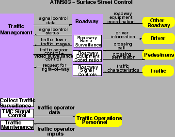 |
This package provide the central control and monitoring equipment, communication
links and the signal control equipment that support local street control or
arterial traffic management.
The various signal control systems dynamically adjusted control plans and
strategies based on current traffic conditions and priority requests.
|