IV.2.1 Closed loop response of liquid level in a storage tank: A case study
Fig IV.7 represents the closed loop block diagram of a storage tank whose liquid level needs to be controlled at a predefined setpoint.
|
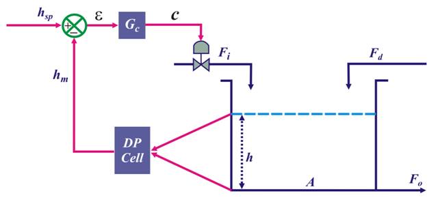 Fig. IV.7: Schematic of closed loop block diagram of storage tank
 We analyze various components of the above,
Process : The process has two inputs and one output. Input ![]() can be manipulated whereas input
can be manipulated whereas input ![]() is the source of disturbance. Output
is the source of disturbance. Output ![]() varies proportionally
with the square root of
the
height of the liquid in the tank as,
varies proportionally
with the square root of
the
height of the liquid in the tank as,![]() The material balance around the tank gives the following model,
The material balance around the tank gives the following model,
(IV.18) |