8.2.6 Individual heat transfer coefficient
In section 8.2.1, we have seen that the overall heat transfer coefficient can be calculated provide the parameters are known including individual heat transfer coefficients. In this, section we will discuss how to find out the individual heat transfer coefficient, which is basically based on the well-established correlations and discussed earlier also.
The heat transfer coefficient (hi) for the tube side fluid in a heat exchanger can be calculated either by Sieder-Tate equation or by Colburn equation discussed in earlier chapter.
However, the shell side heat transfer coefficient (ho) cannot be so easily calculated because of the parallel, counter as well as cross flow patterns of the fluid. Moreover, the fluid mass velocity as well as cross sectional area of the fluid streams vary as the fluid crosses the tube bundle. The leakages between baffles and shell, baffle and tubes, short circuit some of the shell fluid thus reduces the effectiveness of the exchanger.
Generally, modified Donohue equation (eq.8.9) (suggested by D.Q. Kern) is used to predict the ho,
|
(8.9) |
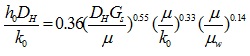
where,
| h0= shell side heat transfer coefficient | |
| Dh= hydraulic diameter of the shell side | |
| k0= thermal conductivity of the shell side fluid | |
| Gs= mass flow rate of the shell side |
The Dh and Gs can be easily calculated if the geometry of the tube arrangement in the shell is known. The tubes may be generally arranged as a square or triangular pitch, as shown in figure 8.14.
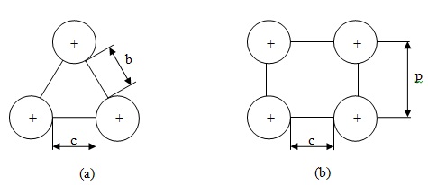
Fig.8.14: Tube arrangement in the shell (a) triangular pitch (b) square pitch
The hydraulic diameter (Dh) for tubes on square pitch 
Dh For 60° triangular pitch= 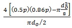
where,
| d0 = outer diameter of tube | |
| p = tube pitch |

where,
| as = shell side flow area |
Shell side flow area can be calculated using baffle information number of tubes in the shell and tube arrangement. If 25% cut baffles are used, that means the shell side flow will be from this 25% area. However we have to reduce the area of the pipes which are accumulated in this opening. So depending upon the information we may determine the shell side fluid flow area. It may also be found out by the following way,

where,
| C = tube clearance | |
| B = baffle spacing | |
| Ds= inside diameter of shell | |
| p = pitch of the tube |