8.2.4 Why multi-pass exchangers?
The simplest type of heat exchangers is double pipe heat exchangers, which is inadequate for flow rates that cannot readily be handled in a few tubes. If several double pipes are used in parallel, the metal weight required for the outer tubes becomes so large that the shell and tube construction, such as 1-1 exchanger will be helpful. In that one shell serves for many tubes, is economical. The heat transfer coefficient of tube side and shell side fluid is very important and the individual heat transfer coefficients must be high enough to attain high overall heat transfer coefficient. As the shell would be quite large as compared to the tubes, the velocity and the turbulence of the shell side fluid is important.
In contrast, the 1-1 exchanger has limitations also. When the tube side flow is divided evenly among all the tubes, the velocity may be quite low, resulting in low heat transfer coefficient. There it may be required to increase the area to have the desired heat exchange for this low heat transfer coefficient. The area may be increased by increasing the length of the tube. However, the tube length requirement may be impractical for a given situation. Thus the number of tubes should be increased without increased the tube length. The increased number of tubes would also provide the increased velocity in the shell side resulting in the higher heat transfer coefficient. Therefore, multi-pass construction is needed, which would permit to use the practical and standard tube lengths. However, the disadvantages are that,
- The construction of the exchangers become complex.
- Parallel flow cannot be avoided.
- Additional friction losses may occur.
It should be noted that generally even number of tube passes are used in multi pass exchanger.
8.2.5 LMTD correction factor
In the earlier chapter, we have seen for co-current or counter current flow system. The average driving force for heat transfer was defined by log mean temperature difference (LMTD). Thus the LMTD can be used for 1-1 exchangers for co-current and counter current. However, for multi pass exchangers (1-2, 2-4, etc.) the fluids are not always in co-current or counter current flow. The deviation for co-current or counter current flow causes a change in the average driving force. Therefore, in order to use true heat transfer driving force, a correction factor is required into the LMTD. Thus, the heat transfer rate can be written as (eq.8.8),
q = UdA(FTΔTm) |
(8.8) |
where,
| Ud = overall heat transfer coefficient including fouling/dirt | |
| A = heat transfer area | |
| FT ΔTm = true average temperature difference. | |
| FT = LMTD correction factor |
It is to be noted that the following assumption have been considered for developing LMTD,
- The overall heat transfer coefficient is constant throughout the exchanger
- In case any fluid undergoes for phase change (e.g., in condenser), the phase change occurs throughout the heat exchanger and the constant fluid temperature prevails throughout the exchanger.
- The specific heat and mass flow rate and hence the heat capacity rate, of each fluid is constant.
- No heat is lost in to the surroundings.
- There is no conduction in the direction of flow neither in the fluids nor in the tube or shell walls.
- Each of the fluids may be characterized by a single temperature, at any cross section in the heat exchanger that is ideal transverse mixing in each fluid is presumed.
FT, the LMTD correction factor can be directly obtained from available charts in the literature. These charts were prepared from the results obtained theoretically by solving the temperature distribution in multi-pass heat exchangers.
Figures 8.12 and 8.13 show the two generally used heat exchangers and their corresponding plots for finding FT. It may be noted that the given figures have the representative plots and any standard book on heat transfer may be consulted for the accurate results.
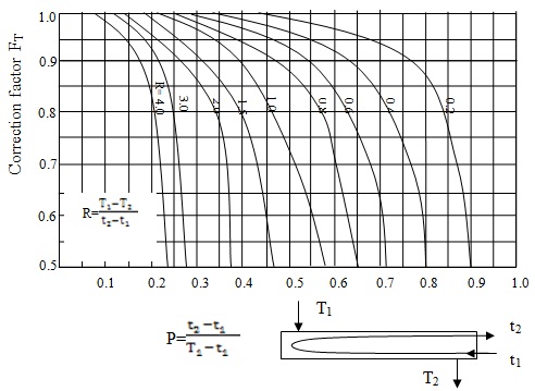
Fig. 8.12: FT plot for 1-2 exchanger; t: cold fluid in the tube; T: hot fluid in the shell; 1: inlet; 2: outlet
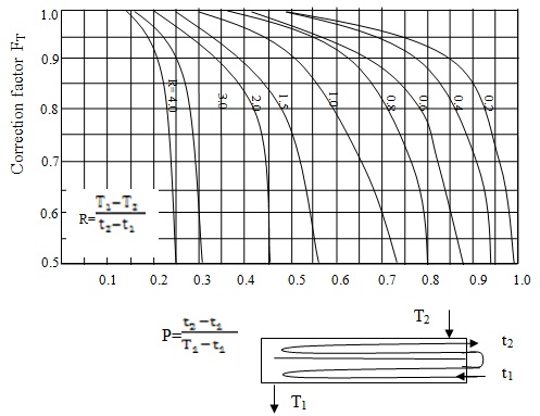
Fig. 8.13: FT plot for 2-4 exchanger; t: cold fluid in the tube; T: hot fluid in the shell; 1: inlet; 2: outlet
It should be noted that in case of condensation or evaporation the correction factor becomes unity (FT =1). While designing a heat exchanger, the rule of thumb is that the FT should not be less than 0.8.