·
The arrangement of a forward feed triple effect evaporator is shown in Figure 3.9 . The energy balance equations in all effects are given below:
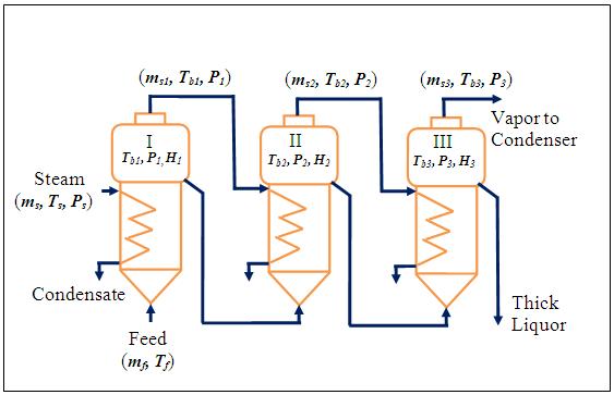 |
Figure 3.9. Flow rates and pressure in a triple effect evaporator ([2] page 399) . |
Effect I : ![]() (3.1)
(3.1)
If the sensible heat of the steam is neglected this equation can be rewritten as-
![]() (3.2)
(3.2)
Effect II : ![]() (3.3)
(3.3)
Effect III : ![]() (3.4)
(3.4)
where,
![]() is the rate of vapor generated in the kth effect
is the rate of vapor generated in the kth effect
mf and ms are the feed and steam flow rate
Hk is the enthalpy of the solution leaving the kth effect at Ts and Ps
![]() is the enthalpy of vapor (steam) generated in the kth effect
is the enthalpy of vapor (steam) generated in the kth effect
Hlk is the enthalpy of liquid in the kth effect
λs is latent heat of steam introduced in the 1st effect at Ps.
![]() and
and ![]() are the latent heats of steam condensation at pressure P1 and P2 respectively.
are the latent heats of steam condensation at pressure P1 and P2 respectively.
If UD1 , UD2 and UD3 are the corresponding overall heat transfer coefficients and A1 , A2 and A3 are the heat transfer area required, then it may be written as -
Effect I: ![]() (3.5)
(3.5)
Effect II : ![]() (3.6)
(3.6)
Effect III : ![]() (3.7)
(3.7)
where,
![]() is the quantity of heat transferred in kth effect
is the quantity of heat transferred in kth effect
![]() is the boiling point of the solution in kth effect at the prevailing pressure
is the boiling point of the solution in kth effect at the prevailing pressure
Ts is the steam temperature entered to the 1st effect
![]() is the boiling point elevation in the kth effect, where
is the boiling point elevation in the kth effect, where ![]() is the boiling point of pure solvent (water) in kth effect at the prevailing pressure
is the boiling point of pure solvent (water) in kth effect at the prevailing pressure
Eqs. 3.2 to 3.7 are solved to calculate the heat transfer area by trial-and-error calculations.