2.1.2. Condenser design
The design of condenser is similar to a typical shell and tube exchangers. A condenser must have a vent for removal of non-condensable gas. The non-condensable gas decreases the heat transfer rate. Condenser usually use a wider baffle spacing of B = Ds (ID of shell) as the allowable pressure drop in shell side vapor is usually less. Vertical cut-segmental baffles are generally used in condensers for side-to-side vapor flow and not for top to bottom. An opening at the bottom of the baffles is provided to allow draining of condensate.
2.1.2.1. Mean temperature difference
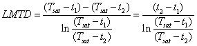
The condensation occurs almost at a fixed temperature (isothermally) at constant pressure for a pure saturated vapor compound. The logarithmic mean temperature difference can be used for condenser design. No correction factor for multiple pass condensers is required . The logarithmic mean temperature difference:
 (1.10)
Where, T sat = Saturation vapor temperature
t1 = Coolant inlet temperature
t2 = Coolant outlet temperature
2.1.2.2. Calculation of heat transfer co-efficient during condensation
Calculation of tube side heat transfer co-efficient (hi): The calculation of heat transfer co-efficient for the cold fluid (coolant) can be performed similarly as discussed in design of shell and tube heat exchanger (heat transfer without phase change). Here it is assumed that the coolant flows the in tube side and the condensing saturated vapor flows in the shell side. If the condensation occurs in the tube side, follow the procedure discussed in next section for shell side calculation.