·
Step #7 . Decide type of shell and tube exchanger (fixed tubesheet, U-tube etc.). Select the tube pitch (PT), determine inside shell diameter (Ds) that can accommodate the calculated number of tubes (nt). Use the standard tube counts table for this purpose. Tube counts are available in standard text books ([3] page 841-842 Table 9; [4] page 308 Table 8.3 ).
Step #9 . Assign fluid to shell side or tube side (a general guideline for placing the fluids is summarized in Table 1.4 ). Select the type of baffle (segmental, doughnut etc.), its size (i.e. percentage cut, 25% baffles are widely used), spacing (B) and number. The baffle spacing is usually chosen to be within 0.2 Ds to Ds.
Step #10 . Determine the tube side film heat transfer coefficient ( hi) using the suitable form of Sieder-Tate equation in laminar and turbulent flow regimes.
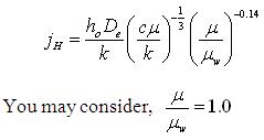
Estimate the shell-side film heat transfer coefficient ( h0) from:
 |
|
Select the outside tube (shell side) dirt factor (Rdo) and inside tube (tube side) dirt factor (Rdi) ([3] page 845 Table 12 ).
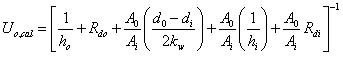
Calculate overall heat transfer coefficient (Uo,cal ) based on the outside tube area (you may neglect the tube-wall resistance) including dirt factors:
 . (1.6)
Step #11 . If ![]() , go the next step # 12 . Otherwise go to step #5, calculate heat transfer area ( A ) required using Uo,cal and repeat the calculations starting from step #5 .
, go the next step # 12 . Otherwise go to step #5, calculate heat transfer area ( A ) required using Uo,cal and repeat the calculations starting from step #5 .
If the calculated shell side heat transfer coefficient (ho) is too low, assume closer baffle spacing (B) close to 0.2 Ds and recalculate shell side heat transfer coefficient. However, this is subject to allowable pressure drop across the heat exchanger.